TM-9-2350-311-20-2 - Page 694 of 828
TM 9–2350–311–20–2
18–24
Change 2
18–4 M145/M145A1 TELESCOPE MOUNT: SYNCHRONIZATION AND ADJUSTMENT
— CONTINUED
d.
Adjusting Synchronization of the M145/M145A1 Telescope Mount – Continued
9
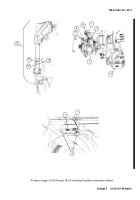
Loosen cap screw (18) on the link connector (19) of the linkage assembly (15). Rotate the adjustment rod
(20) until bubble (4) is centered.
10
Remove M1A1 gunner’s quadrant (1) from M145/M145A1 telescope mount (5) quadrant seats (6). Set
M1A1 gunner’s quadrant (end-for-end correction applied) (breech ring correction factor applied) to zero and
place on breech ring seats (3). Level gun tube.
11
Remove M1A1 gunner’s quadrant (1) from breech ring seats (3). Place M1A1 gunner’s quadrant (end-for-
end correction applied) (breech ring correction factor removed) on M145/M145A1 telescope mount (5) quad-
rant seats (6). Ensure cross-level vial (7) is centered and verify bubble (4) is centered. If not centered repeat
steps 4 through 11 until zero is achieved.
12
Once the M145/M145A1 telescope mount (5) is within tolerance at 400 mils, set 800 mils on M1A1 gunner’s
quadrant (1) (end-for-end correction applied) (breech ring correction factor applied) and place on breech
ring seats (3). Elevate gun tube until bubble (4) is centered in M1A1 gunner’s quadrant.
13
Remove M1A1 gunner’s quadrant (1) from breech ring seats (3). Place M1A1 gunner’s quadrant (end-for-
end correction applied) (breech ring correction factor removed) on M145/M145A1 telescope mount (5) quad-
rant seats (6). Verify that M145/M145A1 telescope mount is within 800
±
0.5 mils.
14
Remove M1A1 gunner’s quadrant (1) from M145/M145A1 telescope mount (5) quadrant seats (6). Set
M1A1 gunner’s quadrant (end-for-end correction applied) (breech ring correction factor applied) to 1200 mils
and place on breech ring seats (3). Elevate gun tube until bubble (4) is centered in M1A1 gunner’s quadrant.
15
Remove M1A1 gunner’s quadrant (1) from breech ring seats (3). Place M1A1 gunner’s quadrant (end-for-
end correction applied) (breech ring correction factor removed) on M145/M145A1 telescope mount (5) quad-
rant seats (6). Verify that M145/M145A1 telescope mount is within 1200
±
0.5 mils.
16
If steps 13 or 15 fail, repeat entire procedure once. If problem is not corrected inspect linkage assembly
(15). Repeat entire procedure, if problem still persist replace M145/M145A1 telescope mount (5).
Back to Top


