TM-9-2350-311-20-2 - Page 701 of 828
TM 9–2350–311–20–2
Change 2
18–33
c.
Disassembly
NOTE
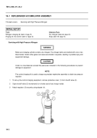
Refer to either the early design or later design illustrations when performing these procedures.
1
Remove air valve cap (6), valve core (7), purging valve stem (8) and strap (9).
2
Remove exit port machine screw (10).
3
Remove machine screw (11), lockwasher (12), electrical cover (13), spacer (14), and LED (15). Discard
lockwasher.
4
Disconnect extension light assembly (16) from rear of M15 quadrant (4).
5
Remove lens (17) and LED (18) from extension light assembly (16).
d.
Assembly
1
Install LED (18) and lens (17) in extension light assembly (16).
2
Connect extension light assembly (16) to rear of M15 quadrant (4).
3
Install spacer (14) onto LED (15).
4
Install LED (15) with spacer (14), electrical cover (13), new lockwasher (12), and machine screw (11).
5
Install exit port machine screw (10).
6
Apply sealing compound to purging valve stem (8) threads.
7
Install strap (9), purging valve stem (8), valve core (7), and air valve cap (6).
LATER DESIGN
17
18
16
10
9
8
7
6
13
15
10
11
12
EARLY DESIGN
14
Back to Top


