TM-9-2350-311-20-2 - Page 698 of 828
TM 9–2350–311–20–2
18–30
Change 2
18–5 M117/M117A2 PANORAMIC TELESCOPE
This task covers:
a.
Inspection
b.
Disassembly
c.
Assembly
INITIAL SETUP
Tools
Artillery and turret mechanic’s tool kit
(SC 5180–95–CL–A12)
Materials/Parts
Lockwasher (item 69, Appx G)
Lockwashers (2) (item 58, Appx G)
Sealing compound (item 28, Appx D)
References
TM 9–2350–311–10
TM 750–116
a.
Inspection
For inspection refer to TM 9–2350–311–10.
b.
Disassembly
NOTE
For removal and installation instructions, refer to TM 9–2350–311–10. For purging and charging
instructions, refer to TM 750–116.
1
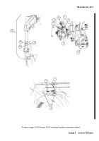
Remove two air valve caps (1), two valve cores (2), two purging valve stems (3) and two straps (4).
2
Remove optical eyeshield (5).
3
Remove two machine screws (6), two lockwashers (7), two electrical covers (8) and two LEDs (9). Discard
lockwashers.
4
Remove machine screw (10).
5
Remove machine screw (11), lockwasher (12), and cap assembly (13). Discard lockwasher.
c.
Assembly
1
Install chain of cap assembly (13) under machine screw (11) and new lockwasher (12). Install cap assembly.
2
Install machine screw (10).
3
Install two LEDs (9), two electrical covers (8), two new lockwashers (7), and two machine screws (6).
4
Install optical eyeshield (5).
5
Apply sealing compound to two purging valve stems (3).
6
Install two straps (4), two purging valve stems (3), two valve cores (2), and two air valve caps (1).
Back to Top


