TM-9-2350-311-20-2 - Page 710 of 828
TM 9–2350–311–20–2
19–2.2
Change 2
19–1 REPLENISHER ACCUMULATOR ASSEMBLY
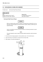
Servicing with High Pressure Nitrogen – Continued
8
Check for blockage and eliminate if necessary.
9
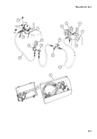
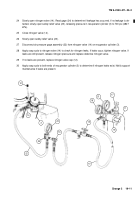
Close shutoff valve (2). Allow nitrogen to bleed from regulator (3) and hose assembly (5).
10
Close pressure regulator valve (7). Turn counterclockwise.
11
Remove nut (10) from gas valve (11).
12
To charge accumulator replenisher (12), connect hose assembly (5) to gas valve (11), but do not tighten at
this time.
13
Open shutoff valve (2) and pressure regulator valve (7) slowly to purge hose assembly (5).
14
Close pressure regulator valve (7) and tighten connection on filling valve (13) by rotating slowly clockwise.
NOTE
Gages labeled 0–15 psi, 0–30 psi, or 0–60 psi are authorized but must be in 1 psi increments.
15
Rotate regulator valve (7) until 7 to 8 psi (48–55 kPa) registers on low pressure gage (9).
16
Close pressure regulator valve (7) and disconnect hose assembly (5) at gas valve (11). Install nut (10) onto
gas valve (11). Apply soap suds to filling valve (13) to check for leaks.
Back to Top


