TM-9-2350-311-20-2 - Page 716 of 828
TM 9–2350–311–20–2
19–8
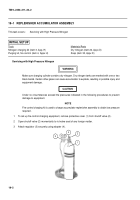
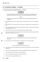
19–2 RECUPERATOR ASSEMBLY — CONTINUED
c.
Servicing with High Pressure Nitrogen (Method Two)
NOTE
Recuperator assembly must be serviced with hydraulic fluid before it is charged with dry nitrogen.
1
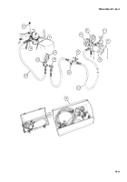
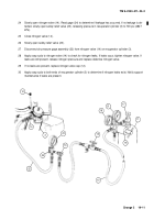
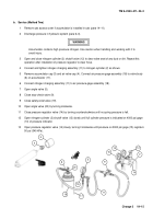
Connect and tighten nitrogen charging assembly (10) to nitrogen cylinder (11) as shown.
WARNING
Dry nitrogen tanks are marked with one or two black bands at the top of the tank. Do not use tanks
without black band. In charging recuperator cylinder, use dry nitrogen. Certain other gases will
cause recuperator cylinder to explode, resulting in possible death or serious injury.
CAUTION
•
Open and close nitrogen cylinder shutoff valve to clear valve seat of any dust or dirt. Repeat
operation after installation of pressure regulator to clear hose.
•
Cannon is shown elevated only for clarification. Cannon must be at zero elevation when check-
ing or charging recuperator cylinder.
2
Remove nitrogen valve cap (12) from nitrogen valve (14).
3
Connect air pressure gage assembly (22) to nitrogen valve (14) on recuperator cylinder (3).
4
Connect nitrogen charging assembly (10) to air pressure gage assembly (22) as shown.
5
Open angle valve (13).
6
Close angle valve (16).
7
Close safety-relief valve (23).
8
Open nitrogen valve (14) by turning counterclockwise.
9
Close pressure regulator valve (18) by turning counterclockwise until no spring pressure is felt.
10
Open nitrogen cylinder (11) shutoff valve (17) slowly until full cylinder pressure is indicated on 4000 psi gage
(21).
11
Open pressure regulator valve (18) slowly, turning clockwise until pressure on 3000 psi gage (19) registers
50 psi (345 kPa).
12
Open stop-check valve (15), allowing nitrogen to enter the recuperator cylinder (3) until gage (24) on the air
pressure gage assembly (22) reads 50 psi (345 kPa). Close angle valve.
Back to Top


