TM-9-2350-311-20-2 - Page 712 of 828
TM 9–2350–311–20–2
19–4
19–2 RECUPERATOR ASSEMBLY
This task covers:
a.
Servicing with Hydraulic Fluid
b.
Servicing with High Pressure Nitrogen – Method One
c.
Servicing with High Pressure Nitrogen – Method Two
INITIAL SETUP
Tools
Nitrogen charging kit (item 3, Appx H)
M3 pump kit (item 9, Appx H)
Purging kit (item 4, Appx H)
Materials/Parts
Hydraulic fluid OHT (item 21, Appx D)
Dry nitrogen (item 22, Appx D)
Soap (item 33, Appx D)
a.
Servicing with Hydraulic Fluid
1
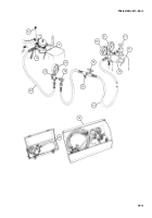
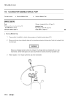
Remove valve cap (1) from check valve (2) at head end of recuperator cylinder (3) inside cab.
CAUTION
Hydraulic fluid must be new. Recuperator assembly must be free of contaminating matter.
NOTE
Rotate head to position drain plug at bottom.
2
Attach M3 oil pump (4) to check valve (2). Fill head until two pins (5) extend not less than 1/8 inch (3.2 mm).
Do not overfill (head requires about 0.7 pint (0.3 l)). After filling, disconnect M3 oil pump.
3
Install valve cap (1).
CAUTION
Loosen cap screws to stop pin before rotating cover to prevent damage to gasket.
4
Loosen two cap screws (6) at front end of recuperator cylinder (3).
3
2
1
Back to Top


