TM-9-2350-311-34-1 - Page 152 of 352
TM 9-2350-311-34-1
Applicable Configurations
Tools
References
Materials/Parts
Equipment Conditions
INITIAL SETUP
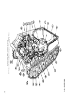
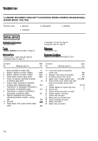
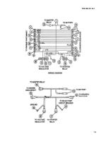
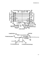
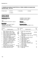
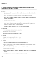
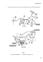
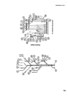
7-6 DRIVER’S BULKHEAD-TO-MASTER RELAY WIRING HARNESS (M109A4/M109A5)
(ENGINE MODEL 7083-7396)
This task covers:
a. Removal
b. Disassembly
c. Assembly
d. Installation
Lockwashers (4) (item 33, Appx F)
M109A4/M109A5
Lockwashers (4) (item 34, Appx F)
Lockwasher (item 35, Appx F)
General mechanic’s tool kit (item 14, A
PPX
c)
TM 9-2350-311-20-1
Electrical tape — black (item 25, Appx B)
Lockwasher (item 23, Appx F)
Batteries disconnected (TM 9-2350-311-20-1)
Lockwashers (2) (item 25, Appx F)
Connector
Wire Connector
Wire
No.
Electrical Lead To:
No. No.
Electrical Lead To:
No.
1
2
3
4
5
6
7
8
9
10
11
12
Battery assembly-to-master relay
81
Aeration detector-to-coolant indicator
352B
Aeration detector-to-coolant indicator
352A
Flame heater-to-flame heater switch
Engine oil pressure transmitter-to-engine
oil pressure gage switch
36
Engine coolant temperature transmitter-
to-engine water temperature gage
33A
Transmission oil temperature transmitter-
to-transmission oil temperature gage
324
Transmission oil pressure transmitter-to-
transmission oil pressure switch
321
Hig/low temperature and pressure
switches/transmitters-to-master
warning light
509
Air cleaner blower motor switch-to-air
cleaner blower motor assembly
415B-76B
Regulator cutoff relay coil energizer
27B
Air cleaner blower motor circuit
415
13
14
15
16
17
18
19
20
21
22
23
24
25
26
27
Master switch voltage regulator
lead
400-4596
Engine starter circuit (starter relay
bilge pump circuit breaker neutral
safety switch)
14/14B/GND
Voltage regulator-to-master relay lead
2
Ground wire
4
Engine bracket disconnect connector
Voltage regulator ground
Engine disconnect
Voltage regulator connector
Starter protection relay
503
Starter protection relay ground
Driver's bulkhead connector-to-starter
protection relay
14C
Driver’s bulkhead
Driver’s bulkhead
Battery positive tenminal
81
Master relay
81
7-16
Back to Top


