TM-9-2350-311-34-1 - Page 160 of 352
TM 9-2350-311-34-1
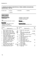
INITIAL SETUP
Tools
Equipment Conditions
Materials/Parts
References
450
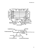
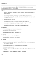
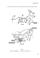
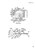
7-8 BULKHEAD-TO-HEADLIGHTS/BILGE PUMP WIRING HARNESS
This task covers:
a. Removal
b. Disassembly
c. Assembly
d. Installation
General mechanic’s tool kit (item 14, Appx C)
Batteries disconnected (TM 9-2350-311-20-1)
Air intake grille opened and secured (TM 9-2350-311-20-1)
Engine exhaust grille and front slope plate removed
Electrical tape — black (item 25, Appx B)
(TM 9-2350-311-20-1)
Engine compartment access cover removed (TM 9-2350-
311-20-1)
TM 9-2350-311-20-1
Connector
Wire Connector
Wire
No.
Electrical Lead To:
No. No.
Electrical Lead To:
No.
1
2
3
4
5
6
7
8
9
10
11
Left fuel pump lead
Left fuel pump
Right fuel pump
Right fuel pump lead
Right upper and lower fuel tank
Right upper fuel tank transmitter lead
Right lower fuel tank transmitter lead
Not Used
Not used
Blackout marker (front light assembly)
Service headlight low beam
76
GND
GND
76
GND
29
31
515
514
20
18
12
13
14
15
16
17
18
19
20
21
22
Service headlight high beam
Bilge pump motor connector
Master relay connector
Bilge pump relay lead
Bilge pump relay energizing circuit
Bilge pump relay power lead
Bilge pump circuit breaker connector
Not used
Bilge pump relay connector
Bulkhead connector
Ground
17
452
459
452
452B
452B
19
7-24
Back to Top


