TM-9-2350-311-34-1 - Page 162 of 352
TM 9-2350-311-34-1
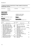
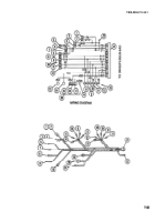
7-8 BULKHEAD-TO-HEADLIGHT/BBILGE PUMP WIRING HARNESS — CONTINUED
a. Removal
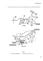
1 Remove two screws (23), two washers (24), two ground leads (5), and two snap-in connectors (6 and 7) from
fuel level transmitters.
NOTE
Powerplant must be removed to disconnect fuel pump leads (TM 9-2350-311-20-1).
2 Remove four snap-in connectors (1 thru 4) from fuel pump.
3 Disconnect 11 quick disconnects (8, 9, 10, 11, 12, and 19) from left and right headlight assemblies.
4 Remove nut (25) and washer (26) from bilge pump circuit breaker and release connector wire (18).
5 Disconnect four electrical connectors (13, 14,20,and 21).
6 Remove screw (27) and washer (28) and release ground wire (22).
7 Remove 15 plastic retainers (29), 15 screws (30), and 15 washers (31) and release wiring harness.
8 Remove wiring harness.
b. Disassembly
1
Remove electrical tape only for sections being disassembled.
2 Separate/isolate wiring harness branches.
3 Disassemble wiring harness branches (TM 9-2350-311-20-1).
c. Assembly
1
Assemble wiring harness branches (TM 9-2350-311-20-1).
2 Apply electrical tape only for sections being assembled.
d. Installation
1 Install wiring harness.
2 Install 15 washers (31), 15 screws (30), and 15 plastic retainers (33) to wiring harness.
3 Install ground wire (22), washer (28), and screw (27).
4 Connect four electrical connectors (13, 14,20,and 21).
5 Install connector wire (18), washer (26), and nut (25) to bilge pump circuit breaker.
6 Connect 11 quick disconnects (8, 9, 10, 11, 12, and 19) to left and right headlight assemblies.
7-26
Back to Top


