TM-9-2350-311-34-1 - Page 156 of 352
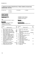
INITIAL SETUP
Applicable Configurations
References
Materials/Parts
Equipment Conditions
TM 9-2350-311-34-1
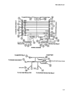
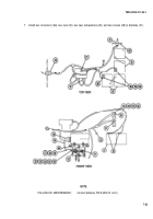
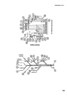
7-7 DRIVER’S BULKHEAD-TO-MASTER RELAY WIRING HARNESS (M109A4/M109A5)
(ENGINE MODEL 7083-7391)
This task covers:
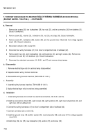
a. Removal
b. Disassembly
c. Assembly
d. Installation
Lockwashers (4) (item 33, Appx F)
M109A4/M109A5
Lockwashers (4) (item 34, Appx F)
Lockwasher (item 35, Appx F)
Tools
General mechanic’s tool kit (item 14, Appx C)
TM 9-2350-311-20-1
Electrical tape — black (item 25, Appx B)
Lockwasher (item 23, Appx F)
Batteries disconnected (TM 9-2350-311-20-1)
Lockwashers (2) (item 25, Appx F)
Connector
Wire
No.
Electrical Lead To:
No.
1
2
3
4
5
6
7
8
9
10
11
12
Battery assembly-to-master relay
81
Aeration detector-to-coolant indicator
352B
Aeration detector-to-coolant indicator
352A
Glow plug controller-to-glow plug switch
486A
Engine oil pressure transmitter-to-engine
oil pressure gage switch
36
Engine coolant temperature transmitter-
to-engine water temperature gage
33A
Transmission oil temperature transmitter-
to-transmission oil temperature gage
324
Transmission oil pressure transmitter-to-
transmission oil pressure switch
321
High/low temperature and pressure
switches/transmitters-to-master
warning light
509
Air cleaner blower motor switch-to-air
cleaner blower motor assembly
415B-76B
Regulator cutoff relay coil energizer
27B
Air cleaner blower motor circuit
415
Connector
Wire
No.
Electrical Lead To:
No.
13
14
15
16
17
18
19
20
21
22
23
24
25
26
27
Master switch voltage regulator
lead
400-459B
Engine starter circuit (starter relay
bilge pump circuit breaker neutral
safety switch)
14/14B/GND
Voltage regulator-to-master relay lead
2
Ground wire
4
Engine bracket disconnect connector
Voltage regulator ground
Engine disconnect
Voltage regulator connector
Starter protection relay
503
Starter protection relay ground
Driver’s bulkhead connector-to-starter
protection relay
14C
Driver’s bulkhead
Driver’s bulkhead
Battery positive terminal
81
Master relay
81
7-20
Back to Top


