TM-9-2350-311-34-2 - Page 31 of 552
TM 9-2350-311-34-2
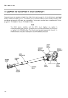
1-14.1 Location and Description of M185 and M284 155mm Cannon Assembly
a.
b.
c.
d.
e.
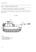
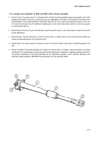
Cannon Tube. The cannon tube (1) is designed with a chamber for the propellant charge and projectile and is rifled
throughout the length of the bore to assure accuracy and repeatability of the flight of the projectile to the target. Inter-
rupted threads on the outside diameter at the breech assembly (2) end of cannon tube facilitate mounting of the can-
non tube into the breech ring (3). Additional threaded areas on the cannon tube allow mounting of the bore evacuator
(4) and muzzle brake (5).
Breech Ring. The breech ring (3) and band (6) connect the cannon tube (1) and recoil system, as well as mount the
breech mechanism.
Bore Evacuator. The bore evacuator (4) vents the cannon tube (1) of gases after a round has been fired, thereby pre-
venting contaminated gases from entering the cab.
Muzzle Brake. The muzzle brake (5) reduces the force of recoil and forward muzzle flash, by deflecting gases to the
side.
Breech Assembly. The breech assembly (2) contains the cannon tube (1) chamber, locking mechanism, and firing
mechanism. The semiautomatic screw block-type breech mechanism is designed for separate loading ammunition.
The principle components of the breech assembly are: the breechblock assembly, carrier assembly, operating crank
assembly, spindle assembly, M35/M49 firing mechanism, and the operating handle.
1-11
Back to Top

