TM-9-2350-311-34-2 - Page 34 of 552
TM 9-2350-311-34-2
1-14 LOCATION AND DESCRIPTION OF MAJOR COMPONENTS - CONTINUED
1-14.2 Location and Description of M178/M182 Mount - Continued
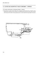
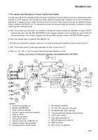
e. Variable Recoil Assembly. The variable recoil assembly (9) compensates for the cannon’s recoil after firing. Principle
components of the variable recoil assembly are variable recoil cylinders (10), buffer cylinder (11), hydraulic replenisher
accumulator (12), and recuperator cylinder (4). The variable recoil cylinders are governed by an actuator assembly
(13) which shortens the length of recoil in relation to the weapon’s elevation. In effect, a shorter recoil is allowed for
higher elevations.
1
2
3
4
VARIABLE RECOIL CYLINDERS. The variable recoil cylinders (10) operate hydraulically to restrict recoil
length and are attached to the cradle assembly (1) and breech ring band (14). Pistons contain orifices to
allow hydraulic fluid to flow from one side of piston to other during recoil. Orifices are tapered to provide a
progressively greater restriction of flow as the weapon approaches full recoil. Rotation of inner orifices regu-
lates the length of recoil. During counter recoil, these same orifices permit a return flow of hydraulic fluid
past the piston.
BUFFER CYLINDER. Buffer cylinder (11) functions to govern action of recuperator cylinder (4) and eases
weapon into battery. Buffer cylinder operates hydraulically and contains a spring-loaded piston which is free
to move rearward during recoil. Buffer cylinder is filled with hydraulic fluid which passes freely through a flut-
ter valve in the piston during rearward movement. During counter recoil, the flutter valve closes and piston
rod contacts the forward face of breech ring band (14). Hydraulic fluid is now permitted only through three
orifices in flutter valve. Restriction of hydraulic fluid flow by piston counteracts action of recuperator cylinder.
ACTUATOR ASSEMBLY. Orifices in the variable recoil cylinders (10) and pistons are alined to provide a pre-
determined orifice area. Actuator assembly (13), which is sensitive to elevation or depression of cannon,
functions through gearing to alter orifice opening within variable recoil cylinders. Shorter recoil results from
reduced orifice openings.
HYDRAULIC REPLENISHER ACCUMULATOR. The hydraulic replenisher accumulator (12) functions to
maintain proper hydraulic fluid level in the buffer cylinder (11) and variable recoil cylinders (10). Hydraulic
fluid is forced through tubes to the buffer cylinder and variable recoil cylinders. A gas valve supplies pres-
sured hydraulic fluid. Hydraulic replenisher accumulator is located in right front of cab, mounted to the wall.
f. Recuperator Cylinder. The recuperator cylinder (4) operates pneumatically and returns the weapon from full recoil to
battery position. During recoil, a piston connected to breech ring band (14) moves within the recuperator cylinder
against a preload of 700 ± 50 psi (4826 ± 345 kPa) of nitrogen at 70°F (21°C). When the recoil force is spent, nitrogen
pressure working against the piston returns the cannon to battery.
1-14
Back to Top

