TM-9-2350-311-34-2 - Page 32 of 552
TM 9-2350-311-34-2
1-14 LOCATION AND DESCRIPTION OF MAJOR COMPONENTS - CONTINUED
1-14.1
1
2
3
4
5
6
Location and Description of M185 and M284 155mm Cannon Assembly - Continued
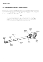
BREECHBLOCK ASSEMBLY. The breechblock assembly (7) locks the projectile and powder charge within
the chamber and remains in closed position until opened by operating cam (8) during later stages of counter
recoil cycle.
CARRIER ASSEMBLY. The carrier assembly (9) mounts the breechblock assembly (7) and firing mecha-
nism (10). A system of springs and gears within the carrier assembly opens and closes the breechblock as-
sembly. The breechblock assembly is opened by power transmitted through gearing from the operating
crank assembly (11). Compression-type coil springs transmit power through gearing to lock the breechblock
assembly after it has been closed by torsion from the closing spring pack.
OPERATING CRANK ASSEMBLY. The operating crank assembly (11), mounted on breech ring (3) rides
within cam paths machined in operating cam (8). A portion of counter recoil force is converted by action of
the operating cam and the operating crank assembly to torque which is transmitted to carrier assembly (9)
gearing.
SPINDLE ASSEMBLY. The spindle assembly (12), mounted on the forward face of breechblock assembly
(7), serves as a seal between chamber and breechblock assembly, preventing entry of gases from the
chamber to the cab at time of firing.
M35/M49 FIRING MECHANISM. The firing mechanism (10) is a continuous pull, percussion type. Impact
force is transmitted through a firing pin in the firing block which strikes a percussion-type primer, detonating
the propellant powder charge. M35 firing mechanisms on M185 cannon assemblies are not interchangeable
with M49 firing mechanisms on M284 cannon assemblies.
OPERATING HANDLE. The operating handle (13) connected to operating crank assembly (11) allows
manual opening and closing of the breech mechanism and is normally kept in stowed position, latched to the
operating handle stop.
1-12
Back to Top

