TM-9-2350-311-34-2 - Page 338 of 552
TM 9-2350-311-34-2
6-14 ASSISTANT GUNNER’S CONTROL ASSEMBLY - CONTINUED
a. Disassembly - Continued
4
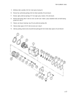
Remove two cap screws (14), two lockwashers (15), three preformed packings (16) and shuttle valve as-
sembly (17) from manifold assembly (13). Discard preformed packings and lockwashers.
5
Remove check valve (18) and preformed packing (19) from manifold assembly (13). Discard preformed
packing.
6
Remove plug (20) preformed packing (21), and electrical cover (22). Discard preformed packing.
b. Assembly
1
2
3
4
5
6
Install electrical cover (22) new preformed packing (21) and plug (20).
Install new preformed packing (19) and check valve (18) in manifold assembly (13).
Install three new preformed packings (16) shuttle valve assembly (17), two new lockwashers (15) and two
cap screws (14) on manifold assembly (13).
Install three new preformed packings (12) manifold assembly (13), five new lockwashers (11), and five cap
screws (10) on hydraulic pumping unit (9).
Secure hydraulic pumping unit (9) to elevation bracket (6) with three new lockwashers (8) and three cap
screws (7).
Secure assistant gunner’s control grip assembly (5) to elevation bracket (6) using hex nut (4), three new
lockwashers (2), three flat washers (3), and three machine bolts (1).
6-74 Change 2
Back to Top


