TM-9-2350-311-34-2 - Page 44 of 552
TM 9-2350-311-34-2
1-14 LOCATION AND DESCRIPTION OF MAJOR COMPONENTS - CONTINUED
1-14.6 Location and Description of Gunner’s and Assistant Gunner’s Control Assemblies - Continued
b.
c.
d.
e.
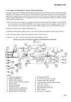
Assistant Gunner’s Control Assembly. The assistant gunner’s control assembly (2) operated by the assistant gunner is
used only to elevate and depress the cannon. To operate with hydraulic power, ELEVATION CONTROL switch (7) on
gunner’s selector switch box assembly (4) must be in NO. 1 MAN position. Moving assistant gunner’s control handle
(11) forward or backward will depress orelevatethecannon inthesame manneras with the gunner’s control assembly.
The assistant gunner’s control handle cannot be used to traverse the cab, however; the traversing ports (TL and TR)
are closed with plugs and the inactive electrical receptacle is covered with an electrical connector cover (12) on both
the gunner’s and assistant gunner’s control assemblies.
Manual Elevating Hand Pump. Manual elevating hand pump (13) mounted on top of assistant gunner’s control handle
(11) is used to manually elevate or depress the cannon. It is essentially a piston type pump containing eight sliding
pistons. Rotating hand crank (14) clockwise causes hydraulic fluid to flow in the manual elevating system, depressing
the cannon. Rotating the hand crank counterclockwise reverses the hydraulic fluid flow and elevates cannon. As the
hand crank is turned, an eccentric pump shaft is rotated, which in turn rotates a slide. As this slide rotates, it cams eight
spring-loaded pistons in sequence so that hydraulic fluid flow is initiated through the manual elevating system. When
the direction of the hand crank is reversed, an integral slide rotates in the opposite direction, reversing caroming se-
quence and flow of hydraulic fluid. The cannon maybe elevated or depressed manually without energizing the power
control system. The rate at which the cannon is elevated or depressed is controlled by the rotation speed of hand
crank.
Shuttle Valve Assembly. The shuttle valve assembly (15), attached to the top of manifold (16), controls pressure of the
manual circuit in case of hand pumping. The pump case is pressurized to keep rotational effort of hand crank (14) at a
minimum. Since low pressure will change to opposite side of the pump when the hand crank rotation is reversed, the
shuttle valve assembly will be shuttled to the opposite side by high pressure of the manual circuit and maintain low
pressure in the pump casing. The shuttle valve assembly will shuttle each time rotation of the hand crank is changed.
Check Valve. The check valve (17) is a one-way valve that permits hydraulic fluid to be directed from the reservoir into
the manual elevating hydraulic system as required, but will not permit hydraulic fluid to return to the reservoir.
1-24
Back to Top


