TM-9-2520-246-34 - Page 46 of 153
TM 9-2520-246-34
Section III. REPAIR (MODEL 3052)
3-7. General.
a.
Clean the exterior of the transmission in
accordance with Chapter 2, section III of this manual.
b.
Refer to Chapter 2, section II of this manual for
troubleshooting procedures.
c.
When a transmission is repaired, it must be
disassembled completely so that the parts may be
thoroughly cleaned and inspected for wear or damage.
Refer to Chapter 2, section III of this manual for
instructions on the repair and rebuilding of the
transmissions.
d.
Disassembly is accomplished in two stages: first,
disassembly into subassemblies; second, disassembly of
the subassemblies. Always use separate containers for
the parts of each subassembly. If more than one
transmission is being rebuilt at the same time,
provision must be made for keeping the parts of each
transmission separate. This is especially important
when some parts are to be used again.
e.
Disassembly of the transmission is accomplished
by following logical step-by-step procedures.
Paragraph 3-8 provides disassembly to the
subassembly level, paragraph 3-9 provides the
disassembly procedures from the subassembly level to
the piece part. Assembly procedures are given only
where special attention to a part or assembly is
required or needed. The assembly of the transmission
is the exact opposite of disassembly except where
otherwise specified for clarity. Always use new gaskets
and seals during assembly.
3-8. Disassembly of Transmission Into
Subassemblies.
a. Clutch Release Assembly.
(1) Unhook the two support springs securing the
release bearing support assembly to the clutch release
yoke and remove from the input shaft bearing cap.
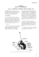
(See fig. 3-16.)
(2) Remove the two capscrews and lockwashers
securing the clutch release yoke to the clutch shaft.
(See fig. 3-16.) Partially slide the clutch release shaft
through the clutch bell housing and remove the two
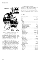
yoke keys from the shaft. (See fig. 3-17.) Remove the
clutch release yoke from the shaft and complete the
removal of the clutch release shaft from the clutch
housing.
(3) Remove the five capscrews and lockwashers
securing the clutch bell housing to the transmission
Figure 3-16. Removal of Clutch Release Bearing
Support Assembly.
case. (See fig. 3-18.) Remove clutch bell housing
gasket from the face of the transmission case.
b. Shifter Shaft Cover.
Position the transmission
shifter shaft in neutral. Remove the eight capscrews
and washers securing the shifter shaft cover, and lift
straight up to clear transmission case; discard the
cover gasket (See fig. 3-19.)
NOTE
When installing shifter shaft cover, position
the shifter shaft in neutral and place the
shifter forks in the mainshaft synchronizer
grooves. (See fig. 3-20.)
Figure 3-17. Removal of Clutch Release Yoke and
Release Shaft.
3-11
Back to Top


