TM-9-2520-246-34 - Page 44 of 153
TM 9-2520-246-34
Section II. DESCRIPTION, OPERATION, AND DATA
(MODEL 3053A)
3-4. General.
The description and operation of the
transmission model 3053A is very similar to that of
transmission model 3052. Therefore, this section will
refer to Section I, where applicable, to avoid
repetition. Only the differences will be given in this
section.
3-5. Description and Operation.
a. Description.
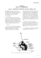
Figure 3-1 shows the transmission
model 3053A used on the 2½-ton, 6x6, multifuel
engine vehicles without front winch equipment. This
transmission can also power a front winch by means
of a power takeoff mounted on the left side of the
transmission. (See fig. 3-2.) The construction of
transmission model 3053A is almost identical to that
of transmission model 3052, except for the fourth and
fifth gear arrangements. This difference is shown by
comparison between figures 3-13 and 3-6 and figures 3-14
and 3-8.
b. Operation.
(1) Power Flow.
Power flow for transmission
model 3053A is the exact opposite of the power flow
for transmission model 3052. See figure 3-15 for the
difference in power flow. See figure 3-12 for first-,
second-, and third-speed power flow.
(2) Fourth-Speed Power Flow.
Power is
transmitted from the input gear, which is coupled to
the mainshaft by the fourth-fifth synchronizer, directly
to the mainshaft. Because the interlocking action of
the synchronizer in effect makes one continuous shaft
of the input shaft and mainshaft, the drive here is
direct; i.e., a 1-to-1 ratio. (See fig. 3-15, view A.)
(3) Fifth-Speed (Overdrive) Power Flow.
Power
is transmitted by the countershaft fifth-speed
(overdrive) gear to the mainshaft fifth-speed
(overdrive) gear, which is coupled to the fourth-fifth
(overdrive) synchronizer and to the mainshaft. (See fig. 3-
15, view B.)
3-6. Data.
National stock number . . . . . . . . . . 2520-00-884-4833
Ordnance number . . . . . . . . . . . . .
. . . . . . . . .
10872096
Make
. . . . . . . . . . . . . . . . . . . . . . . . . . . . . .
. . . . .
Spicer
Model . . . . . . . . . . . . . . . . . . . . . . . . . . . . . . . . . . 3053A
Type
. . . . . . . . . . . . . . . . . . . . . . . . . . .
Synchromesh
Speeds:
Forward . . . . . . . . . . . . . . . . . . . . . . . . . . . . . . . . . . . 5
Reverse . . . . . . . . . . . . . . . . . . . .
. . . . . . . . . . . . . . . . 1
Gear types:
Input
. . . . . . . . . . . . . . . . . . . . . . . . . . . . . . . .
Helical
Mainshaft (except first-reverse) . . . . . . . . . Helical
Mainshaft first-reverse . .
. . . . . . . . . . . . .
. . . .
Spur
Countershaft (except first)
. . . . . . . . . . . . . .
Helical
Countershaft first . . . . . . . . . . . . .
. . . . . . . . . .
Spur
Reverse idler . . . . . . . . . . . . . . . . . . . . .
Spur-helical
Bearings:
Input shaft
. . . . . . . . . . . . . . . . . . . . . . .
Ball
Mainshaft front . . . . . . . . . . . . . . . . .
Straight roller
Mainshaft rear
. . . . . . . . . . . . . . . . . . . . . . . . . . . . . .
Ball
Countershaft front . . . . . . . . . . . . .
Straight Roller
Countershaft rear . . . . . . . . . . . . . . . . . . . . . . . . Ball
Reverse idler . . . . . . . . . . . . . . . . . . .
Straight roller
Input shaft size:
Spline diameter . . . .
. . . . . . . . . . . . . . . . . .
1.499 in.
Number of splines
. . . . . . .
. . . . . . . . . . . .
. . . . . . .
10
Full length of splines . . . . . . . . . . . . . . . . . 2.375 in.
Mainshaft (output end) size:
Spline diameter
l . . . . . . . . . . . . . . . .
. . . . .
1.499 in.
Number of splines . . . . . . . . . . . . . . . . . . . . . . . . . . 10
Full length of splines . . . . . . . . . . . . . . . . .1.906 in.
Gear ratios:
First speed . . . . . . . . . . . . . . . . . . . . . . . . . . 5.02 to 1
Second speed
. . . . . . . . . . . . . . .
. . . . . . . . .
2.78 to 1
Third speed
. . . . . . . . . . . . . . . . . . . . . . . . .
1.62 to 1
Fourth speed . . . . . . . . . . . . . . . . . . . . . 1.00 to l.00
Fifth speed (overdrive) . . . . . . . . . . . . . . . . 0.79 to 1
Reverse . . . . . . . . . . . . . . . . . . . . . . . . . . . . . 4.90 to 1
3-9
Back to Top


