TM-9-2815-200-35
ENGINE, WITH CONTAINER:TURBOSUPERCHARGED, DIESEL ,FUEL INJECTION ,90-DEGREE “V” TYPE, AIR - COOLED ,12 - CYLINDER , ASSEMBLY ;MODELS AVDS-1790-2M (2815-856-4996), AVDS-1790-2A AND AVDS-1790-2AM (2815-856-9005)
TECHNICAL MANUAL; DIRECT SUPPORT, GENERAL SUPPORT AND DEPOT MAINTENANCE MANUAL INCLUDING REPAIR PARTS AND SPECIAL TOOLS LISTS
TM-9-2815-200-35 - Page 376 of 779
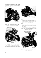
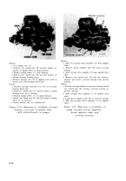
Remove
1. Cut locking wire (A).
2. Remove drilled head bolt (B) and lock plate.
3. Remove five slotted nuts (C) and flat washers at-
taching pressure housing cover to pressure housing.
4. Separate and remove cover (D) from housing.
Install
1. Position pressure housing cover (D) on pressure
housing.
2. Install five slotted nuts (C) and flat washers securing
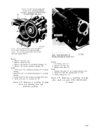
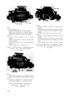
Remove
1. Remove impeller drive shaft (A) from pressure
housing.
2. Cut locking wire and remove four slotted nuts (B) and
flat washers attaching scavenge oil pump inlet scoop on
housing.
3. Remove inlet scoop (C). Do not remove screens.
Install
1. Position scavenge oil pump inlet scoop(C) on pressure
housing.
2. Install four slotted nuts (B) and flat washers securing
inlet scoop on housing and install locking wire securing
cover on housing.
3. Position lock plate on cover and install drilled head
bolt (B).
4. Install locking wire (A) securing nuts.
Figure 6-80. Removing or installing pressure
housing cover (FSN 2815-895-6430
oil pump).
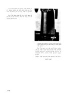
Remove
1. Remove driven impeller (A) from pressure housing.
2. Remove drive impeller (B) from impeller drive shaft.
Install
1. Install drive impeller (B) on impeller drive shaft.
2. Install driven impeller (A) in pressure housing.
Figure 6-81. Removing or installing oil
pump piston cooling drive and
driven impellers.
nuts.
3. Install impeller drive shaft (A) in pressure housing.
Figure 6-82. Removing or installing scavenge
oil pump inlet scoop (FSN 2815-679-4965
oil pump).
6-8 2
Back to Top

