TM-9-2815-200-35
ENGINE, WITH CONTAINER:TURBOSUPERCHARGED, DIESEL ,FUEL INJECTION ,90-DEGREE “V” TYPE, AIR - COOLED ,12 - CYLINDER , ASSEMBLY ;MODELS AVDS-1790-2M (2815-856-4996), AVDS-1790-2A AND AVDS-1790-2AM (2815-856-9005)
TECHNICAL MANUAL; DIRECT SUPPORT, GENERAL SUPPORT AND DEPOT MAINTENANCE MANUAL INCLUDING REPAIR PARTS AND SPECIAL TOOLS LISTS
TM-9-2815-200-35 - Page 555 of 779
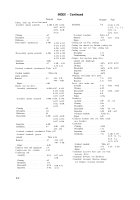
Table 8-6.50 Hour Quality Control Test
Run No.
1
2
3
4
5
6
7
8
9
10
11
12
13
14
15
16
17
18
19
20
21
22
23
24
Time
1 hour
½ hour
1½ hour
½ hour
2
hours
½ hour
2 hours
1 hour
5 hours
1 hour
5 hours
1 hour
5 hours
1 hour
5 hours
1 hour
5 hours
1 hour
5 hours
1 hour
5 hours
5 min.
5 min.
5 min.
8-8. General
This section of the manual covers
Engine Speed
½ load
Idle
Full load
Idle
½ load
Idle
Full load
Idle
Full load
Idle
Full load
Idle
Full load
Idle
Full load
Idle
Full load
Idle
Full load
Idle
Full load
Full load
Full load
Full load
Section II. ENGINE AND CONTAINER
the reusable
metal container, Army Part No. 10912269, and
procedures for preservation of engines fo r
storage. The container is designed to provide
substantial protection against damage for the
engine during transit, and also against en -
vironmental deterioration over extended periods
of storage. The following instructions will cover
the removal of the engine from the container,
reconditioning and testing of the container,
preservation of engines for storage, the in-
stallation of the engine in the container, sealing,
and periodic inspection.
8-9.
Disassembling
Container an d
Removing Engine
a.
Prior to disassembling the metal container,
the pressure must first be released through the
Rack Setting
2000 rpm
700 rpm
2400 rpm
700 rpm
2000 rpm
700 rpm
2400 rpm
700 rpm
2400 rpm
700 rpm
2400 rpm
700 rpm
2400 rpm
700 rpm
2400 rpm
700 rpm
2400 rpm
700 rpm
2400 rpm
700 rpm
2400 rpm
2200 rpm
2000 rpm
1800 rpm
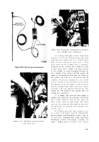
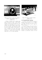
pressure relief valve (fig. 8-7), located in a
recessed insert on the end of the container.
Remove all nuts, lock washers and bolts securing
the upper and lower container sections together.
Remove upper section of container and retain
sealing gasket (providing it has not bee n
mutilated and is still serviceable). Remove the
seven bolts and lock washers securing the engine
to the transmission adapter support flange and
the four nuts and lock washers securing the
engin e
mounting brackets to the mountin g
flanges on the engine support cross members.
Remove all engine parts previously removed
from the engine and secured separately in the
container. In cases where the engine has been
returned for rebuild, forward these parts to the
proper reconditioning area.
8-1 3
Back to Top


