TM-9-2815-202-34 - Page 33 of 670
TM 9-2815-202-34
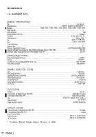
COOLING SYSTEM
Type . . . . . . . . . . . . . . . . . . . . . . . . . . . . . . . . . . . . . . . . . . . . . . . . . . . . . . . . . . . . . . . . . . . . . . . . . . . . . . . . . . . . . . . . . . . . . . . . . . . . . . . . . . . . . . . . . . . . . . . . . . . . . . . . . . . . . . .
Liquid
Capacity
. . . . . . . . . . . . . . . . . . . . . . . . . . . . . . . . . . . . . . . . . . . . . . . . . . . . . . . . . . . . . . . . . . . . . . . . . . . . . . . . . . . . . . . . . . . . . . . . . . . . . . . . . . . . . . . . . . . . . . . . . . . 31 qts. (29.3 L)
Normal Operating Temperature . . . . . . . . . . . . . . . . . . . . . . . . . . . . . . . . . . . . . . . . . . . . . . . . . . . . . . . . . . . . . . . . . . . . . . . . . . . . . 160-185°F (71-85°C)
Maximum Top Tank Temperature . . . . . . . . . . . . . . . . . . . . . . . . . . . . . . . . . . . . . . . . . . . . . . . . . . . . . . . . . . . . . . . . . . . . . . . . . . . . . . . . . . . 230°F (110°C)
Coolant Flow (at 2300 RPM) . . . . . . . . . . . . . . . . . . . . . . . . . . . . . . . . . . . . . . . . . . . . . . . . . . . . . . . . . . . . . . . . . . . . . . . . . . . . . . . . .143 GPM (541 L/min)
Thermostats (Models 7083-7395 and 7083-7398) . . . . . . . . . . . . . . . . . . . . . . . . . . . . . . . . . . . . . . . . . . . . . . . . . . . . . . (2) Blocking Type
Thermostats (Models 7083-7391, 7083-7396, and 7083-7399) . . . . . . . . . . . . . . . . . . . . . . . . . . . . . . . . . Remote mounted
DRIVE RATIOS AND ROTATION
Right Camshaft . . . . . . . . . . . . . . . . . . . . . . . . . . . . . . . . . . . . . . . . . . . . . . . . . . . . . . . . . . . . . . . . . . . . . . . . . . . . . . . . . . . . . . . . . . . . . . . . . . . . . . . . . . . . . . . . . . . . 1.00:1 CCLW
Left Camshaft . . . . . . . . . . . . . . . . . . . . . . . . . . . . . . . . . . . . . . . . . . . . . . . . . . . . . . . . . . . . . . . . . . . . . . . . . . . . . . . . . . . . . . . . . . . . . . . . . . . . . . . . . . . . . . . . . . . . . . . 1.00:1 CLW
Blower Drive (Models 7083-7391,7083-7395, and 7083-7396) . . . . . . . . . . . . . . . . . . . . . . . . . . . . . . . . . . . . . . . . . . 1.95:1 CLW
Blower Drive (Models 7083-7398 and 7083-7399) . . . . . . . . . . . . . . . . . . . . . . . . . . . . . . . . . . . . . . . . . . . . . . . . . . . . . . . . . . . . . . . 2.05:1 CLW
Starter Motor
. . . . . . . . . . . . . . . . . . . . . . . . . . . . . . . . . . . . . . . . . . . . . . . . . . . . . . . . . . . . . . . . . . . . . . . . . . . . . . . . . . . . . . . . . . . . . . . . . . . . . . . . . . . . . . . . . . . . . . . . . 9.27:1 CLW
Fuel Pump (Models 7083-7391, 7083-7395, and 7083-7396) . . . . . . . . . . . . . . . . . . . . . . . . . . . . . . . . . . . . . . . . . . . . . 1.95:1 CLW
Fuel Pump (Models 7083-7398 and 7083-7399) . . . . . . . . . . . . . . . . . . . . . . . . . . . . . . . . . . . . . . . . . . . . . . . . . . . . . . . . . . . . . . . . . 2.05:1 CLW
WaterPump . . . . . . . . . . . . . . . . . . . . . . . . . . . . . . . . . . . . . . . . . . . . . . . . . . . . . . . . . . . . . . . . . . . . . . . . . . . . . . . . . . . . . . . . . . . . . . . . . . . . . . . . . . . . . . . . . . . . . . .
1.00:1 CCLW
Table 1-1 Engine Physical Data
Model
7083-7391
7083-7395
7083-7396
7083-7398
7083-7399
Length - in.
42.4
5.35
42.4
55.5
42.4
(cm.)
(108)
(136)
(108)
(141)
(108)
Width - in.
54.9
40.7
54.9
41.2
57.8
(cm.)
(139)
(103)
(139)
(105)
(147)
Height - in.
41.6
40.8
41.6
40.8
41.6
(cm.)
(106)
(104)
(106)
(104)
(106)
Weight - lb.
2495
2495
2495
2617
2602
(Kg.)
(1132)
(1132)
(1132)
(1187)
(1180)
Section Ill. PRINCIPLES OF OPERATION
1-11. PRINCIPLES OF OPERATION.
The diesel engine is an internal combustion power unit where
the heat energy of fuel is converted into work energy inside the cylinder. This particular engine has a
two stroke cycle (sometimes called a two cycle). A two stroke engine completes one cycle (intake,
compression, power, and exhaust) every time the piston goes up and down - up being one stroke and
down being the return stroke. The air intake and exhaust functions are accomplished during the
compression and power strokes.
Change 1
1-11
Back to Top

