TM-9-2815-205-24 - Page 196 of 856
INSTALLATION - Continued
8.
Securely tighten tube assembly (Figure 2, Item 14) and tube assembly (Figure 2, Item 18). Torque adaptor
(Figure 2, Item 24) to 14–16 lb-ft (19–22 N·m). Torque bolt (Figure 2, Item 12) and bolt (Figure 2, Item 21) to
13–17 lb-ft (18–23 N·m).
9.
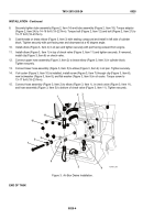
Coat threads on brass elbow (Figure 3, Item 3) with sealing compound and install in left side of cylinder
block. Tighten securely with port facing rear and downward at a 45 degree angle.
10.
Install elbow (Figure 3, Item 4) in oil pan and tighten securely with port facing outward from engine.
11.
Install elbow (Figure 3, Item 1) in top of check valve (Figure 3, Item 11) and tighten securely. If removed,
install clip (Figure 3, Item 6) on check valve.
12.
Connect upper hose assembly (Figure 3, Item 2) to brass elbow (Figure 3, Item 3) in cylinder block.
Tighten securely.
13.
Connect lower hose assembly (Figure 3, Item 5) to elbow (Figure 3, Item 4) in oil pan. Tighten securely.
14.
If oil cooler (Figure 3, Item 10) is installed, install screw (Figure 3, Item 7) through clip (Figure 3, Item 6),
new lockwasher (Figure 3, Item 8), and flat washer (Figure 3, Item 9) in oil cooler. Torque screw to
13–17 lb-ft (18–23 N·m).
15.
Connect hose assembly (Figure 3, Item 2) to elbow (Figure 3, Item 1), in check valve (Figure 3, Item 11),
and hose assembly (Figure 3, Item 5) to bottom of check valve (Figure 3, Item 11). Tighten securely.
2
1
3
4
5
6
7
8
9
10
11
MAINT_080
Figure 3.
Air Box Drains Installation.
END OF TASK
TM 9-2815-205-24
0028
0028-4
Back to Top


