TM-9-2815-205-34 - Page 21 of 596
TM 9-2815-205-34
s.
t.
u.
v.
w.
x.
y.
z.
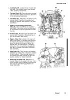
Camshafts (19).
Located on top of each cylin-
der bank. They actuate injector and exhaust
valve operating mechanisms.
Cylinder Block (20).
Being the main structural
part. It provides rigidity and ensures alinement
of all load bearing assemblies.
Crankshaft (21).
Attached to the bottom of the
cylinder block. It transfers the engine load
through the flywheel and supplies oil to piston
assemblies.
Piston and Connecting Rod Assem-
blies (22).
Three assemblies are located in
each bank. Pistons are cooled and lubricated
by oil pressure fed up through drilled connect-
ing rods.
Oil Pump (23).
Mounted inside the lower front
engine cover. It pumps oil throughout the en-
gine for lubrication and cooling.
Bypass Valve (24).
Located in the rear end
plate of the blower, it increases fuel efficiency
by reducing the amount of engine power re-
quired to operate the blower at above idle
speeds when the turbocharger is supplying
sufficient air flow to sustain an adequate air/
fuel ratio for models 5063-5392, 5063-5393
and 5063-539L.
Glow Plugs (25).
They improve cold weather
statability by heating the combustion chamber
of each cylinder. The glow plugs screw into
the cylinder head and protrude into the com-
bustion chamber for model 5063-539L.
Glow Plug Controller (26).
Attached to a
bracket located on the upper front cover, it is a
control module used to regulate the glow plug
duty cycle for cold starting applications on
model 5063-539L.
Change 1
1-9
Back to Top

