TM-9-2815-220-24 - Page 1213 of 1563
TM 9-2815-220-24
CONNECTING ROD ASSEMBLY REPAIR
0143 00
DISASSEMBLY (Continued)
NOTE
Connecting rods and caps are stamped with a location number on the
side of one of the bosses.
For example, "1R" would identify
connecting rod and cap for number one cylinder on the right bank.
Identifying serial numbers are located on the side opposite of the
cylinder location numbers.
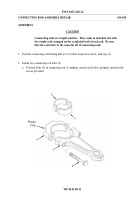
2. Identify bearing (5) location.
a. Mark the two bearing halves (5) with a grease pencil or suitable marker to indicate their
location.
For example, the connecting rod bearing half (A) for cylinder "1R" should be
marked "1RR" {1 right rod} and the cap bearing half (B) should be marked "1RC" {1 right
cap}.
NOTE
If connecting rod (1) or cap (4) markings are obliterated, stamp
connecting rods and caps so that they can be installed in their original
positions.
5-B
5-A
4
1
WP 0143 00-3
Back to Top


