TM-9-2815-220-34 - Page 264 of 532
TM 9-2815±²20±34
( 2) lrutaLiTIon.
(a)
Aline bushIng, liner± or bush²nG-type
beaRinG in cast²nG OR reTa²n²nG caGe. PReSs in³´
pLace with a suI³µbLe press²nG aRbOR
(b)
·ELect prOper drill s²ze fOr ²nsTµllatIOn
Of bearing Re³µ²n²nG p²ns¶ DR²ll thrOuGh beaR²ng
and In³´ cast²nG Or Re³¸ining caGe ¹´ the prOpeR
depth ºO that »He pIn w²lL be flUsh with the bear²ng
suRface
af¼r
ins³µLLat²On
DR²ve
re¹½²ning pIn
thrOugh
bearIng and ²n³´ castIng Or re¹¾²n²nG
cage¿ Cut Off any pOrt²On Of ³he À²n that ex¹Ánds
abOve bearingÂ
±c²
Ãeam Or buRn²sh
bush²ng LIner±
Or
bush²nGÄtype bear²ng ³´
s²Ze
spec²fied
²n
apÅ
pROpria³Æ Repa²r s³andarÇs ¹abLe
³d´
CLean repaIRed parÈ thOrOughLy befOre
assembLy OR ²nstalLat²on
±² OI³ Sea ´
ÃepLace aLl O²É seaÉs at enGIne repair
ÊuRinG f²eld repair± replace OIL seaL when thin
feather edGe Ës damaGed OR when seal has becOme
haRd OR bRittleÌ
( 1) REmµvaL
Press OR pRy Çamaged O²l seaL
FrOm casting Or adapÍRÎ
( 2) Repa·¸²
When OiL seal bORe in castinG OR
adaptÁr ²s buRed OR Çamaged ¹´ a pOint wheRe an
OiL-t²ght seal ²s impOssIbleÏ repa²r Or Replace castÐ
²ng OR aÇapTÑRÒ ÃemOve sLiGht nIcks± buRs± and
scra³Óhes fROm Oil seal bOre In casting Or adapter
w²th crOcus cLOth dipped in dry-cleaning sOLvent Or
mIneraÔ ÕpiriÖ×½ paint thinneR
(8) ¹º»AL¼4½¾µN²
Ønst½lL new Oil seaL ²n bOre Of
cast²nG OR adapter
3-39. ReplaCEment
of
HELiµa¶·¸o¹º
anD
ThrEaDED InsEr»s
a¿ GÀÁeÂa³Ã
ÃepÙace aLl heL²caL-ÚOiL and scRew
thRead inseR³Û which ÇO nOt f²t secuReLy in the castÐ
InG OR when castinG ³HReads have becOme GalleÇ Or
st²ppedÂ
b.
RepÄacÀmÅÁÆÇ
ÃepÜace
alL
unserviceabÝe
hel²caÝ-cOiL and screw thRead ÞnseRTÛ in ßhe same
manner as Outl²ned in the fOlLOwing ÞnstructIOn
àOR ánâtructiOnaL purpOses heã²caLäÚO²L Inserå in
the cyl²nder assembly w²lL be reælaced
È
1¼
çse a d²amOnd-shaped punch »´ remOve
¹he stakeèÏ serRaTed-³´OTH type sect²On Of ²Neét
(fiG
8-ÉÊË)
êrOm ßhe thRead ²ë cyLinder casting
Ì 2)
ìní³îLL scRew ïhRead eXßRaðß´r
ñ
Part òOó
³´6µ
77¶·¸¶¹
Inô ²nsertÎ ÃemOve ²nsert by appLyIng
cOnstant pRessure wh²le turnIng ex¹õacör cOun÷
tÁRcLOckwise unt²l ²nseRt ²s RemOved
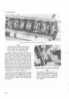
Figure
3-142.
Remº»in¼
hElIcaL-o±l thReA
½INrt fom
Cy²³nde´ aUemb²Y µ¶·ns
arEw thrEA Exl¾Ot¿rÀ
'
ÁÂÃÄ
øhe spec²aL cO²l screw LOck inserteR »OOLs
Lis³Æd ²n spec²aL ³´OL ³abLe
2-1
must be
used when
²ns¹aLɲnG
the
seLfùLOcking
thRead type inseRú¶ ûüese spec²aL iný
seR¹ers are fuRtheR þdentifieÇ by painÿd
aReas marked either with a Red Āandãe
Or a Red strIpe arOund ¹he BOdyā
( 8)
ûhread new InseRt (êigÂ
8-1Í3)
int´ ¹Āe
ßhReaded Guide OF inseR¹er PaRt ĂO
MÎÏ-Ð-21Ñ0
by sLOwly turnIng the p²LOt untIL insert ²s fLush w²»H
ßhe end Of the tăOlÌ Ønsert the pILOt Of ³he screw
thRead inseRïÁR PaRï òO
MÒÓ-Ô-ËÕ80
in¹´ Ąe
thReaded hOle ²n cylindeõÏ w²¹h face Of ßHe ąnâeR³ÆĆ
rest²nG sOLidly aga²nst the casting as shOwn
È Í)
·LOwãy tuRn handLe Of piLOï cLOcKwise untiã
nO êurther Res²sTance ²s feLtć øhe inseRï wILL ßhen
be fLush w²th cyL²nder cast²ngĈ ÃemOve iĉsertÆr
anÇ bReak Off heÉicaL-cOiL ¹µngÂ
)
)
)
Back to Top


