TM-9-2815-220-34 - Page 310 of 532
TM 9-2815-220-34
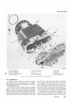
fan shroud brAcket mounting FlAnge on the
exhAUst poRT sIde oF the cyLInde± Assemb²y (fig.
3-192).
See tAbLe
3±²2
fOr ove±sIze assembLy iden-
t³FicAtioN nUmber´
t±\²³´6µP
Figure3·19. LocatIOn Of sTaNdaRD A±D ²vE³S´ze Cylµ¶¸¹r
A"sembºy »¼eNt½¾¿caÀi²Á NUmBÃrÄÅ
ÆÇBÈÉ ÊË1$Ì ÆABUÍAÎÏÐÑ ÒÓ ÔÕAÖDAr× ÇØD ÙveRSÚZe ÛyºÏ±Der ÜÝÞEmBÍY ßDEàáÕâãCAÕÚ²àä åUmBEræ
Pat
çèMéê³
1095±304
1095±²0³·1
109´±²0³µ2
¶09´1²0¸-²
10¹´1²0¸-¸
Bore sizE
STAND±Rd
0.0±0
OV²³´IZ²
0º020
µv¶RS·¸
0»0²0
µv¹RSº¸
0¼0¸0
µv¶RS»¸
(³´
Cy²³nde± bo±es mAy taper sLIghtLy At the
heAd end (At room temperAture)µ ¶he tapered
sect³on expANds And Is essentiALLy st±A³ght at
ope±at³Ng tempe±AtU±e·
µ2)
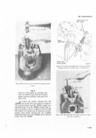
W³th cy²iNde± at room temperAtu±e, tAKe
two cyLInder bo±e meAsurements at point ¸
th±oUgh E, repAIr stAndA±ds ¹tAb²e
3±13)
And Fºgµ
3±³93
MeAsu±e dIAmeter ApproxImAte²y pa±aLLeL to
²³ne of vALves, and then taKe meAsurement
de»
grees to Fi±st measU±ement· ¸ve±Age the meas-
Urements¼
NO·E: ALl OImeNSIONs ¸HOWN
¼
ARE In INCHE¸.
D
a
B
c
¹o ·· Oº
I
»¼½¾
J
CF ½l<L¾H
6¿À¾
Á¼7¾
1
0
¼
5
0
TA126148I
ëÚgìre
½µ¾¿ÀÁ
ÛyíîNDeï bOre ¼Úme>ðñOnòó
(3)
HeAd eNd averAge meAsuremeNts mUst Not
eXceed ½¾ange end averAge meAsU±ementsµ
(Â)
CompA±e t¿e measÀ±ements tAKen
90
deÁ
g±ees Apa±t EAch two meAsÃrements mUst be
ÄÅthin
0·003
³nches of eAch othe±µ ÆF the dIFFe±enÇe
exceeds
0¸003
³nches, the cy²³nde± ³s oUtÈoFÈroUNd
and mUst be marKed for repaI±·
ÃÄ
¹00
ÅhÆÇgÈ É
B¿Àe ÁÂÃmEÄÅÆ
´Â76±- ´ÃÄ5²
5Å7Ʊ
Ä
5ºÄƲ
´ÇÈ7±µ´ÇÄIJ
´É78±Ê5ÇÄ83
´Ë7¹±Ì ´ÂÄÍ
µ5)
Ænspect ¢amshAFt beA±INg Inserts
(35,
FIgµ
3º³90)
Ér pIttIng, gALlIngÊ bU±s, And NIcKsË Ìine
sc±atches on beA±Ing ³nse±ts Are not cAuse ɱ ±e»
ject³onµ P³tting or Any other Ío±m of dest±uct³on to
Î the beA±ing surface Is cause For reJectIonÏ Sp±ead A
thIn coat oF бussIAn bLue ove± the bAcKs of the
beA±ing Inse±ts And instALL In theI± or³g³na² ²ocA»
t³oN on cyLInde± Assemb²y And rocKe± box coverµ
SecU±e ±ocKe± box cove± to cy²³nder assembÑy ÄÒth
FOU± bolts
(20)
And washe±s
µ2³)»
Óo±que t³ghten to
275¼325
Inµ Lbs¼ ChecK tÔe insert dIAmeter of bear»
Ing inse±ts
½35)
ÕIth a diAL bo±e IndIcAto± Aga³nsÖ
the LImIts spec³FIed In repAi± stAndA1×ds (tAbLe
3¾³3)¿
Øep²ace bea±ing Inse±ts thAt do not meet these
reQU³remeNtsÙ
ÊËÌ
Ænspect cy²Inde± heAd And bA±reÚ coo²Ing
F³ns ÛÜÝ× possibÞe ±epAI± ¹pA±a
3±?)À
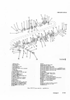
d. Valve Rocker A±m Co²e1·s ³nd AssO´i³ted
Paµts.
µ³Á
V³lve ro¶Ke¸ arm ´o¹er.
Ænspect vA²ve rocKer
sUppoßt cove±
µ15Â
Fàgá
3º190)
Ér cracKs· ânspãct
camshaFt beA±Ing Inse±t su±face For gaLLIngä pitå
tIng, bu±s, and nIcKsµ ChecK cove± AgAInst ²imIts
specIF³ed In repAIr standa±ds (tAb²e
3ÃÄ3)Å
ChecK
vA²ve AdæUstiNg Access cçve±
ÍÎ,
Figµ
3ó90)
Íor
cracKs and ÍorwarpageË ØepLAce cyLInder Assemb²y
when cove± Is unse±viceabLeµ
(2)
V³lve µoºKer ³»Ms¼
ènspect vA²ve rocKe±
arms
(29
and
30)
fOr crAcKs, UsIng a mAgnIFyIng
g²Ass ¹éve power magN³fIcatIon mIN³mUmê and A
st±oNg lIghtµ ÆNspect the bUshIngÈtype beArIng
)
±
Back to Top


