TM-9-2815-220-34 - Page 33 of 532
lined, steel-backed, spLIT bushing TyPe bear±Ng is
pressed ±nTo the pis²on pIn end of The rod. ³he
rep´aceaB´e pµ'ecisIon connecTing Rod BearinGs are
The stee´¶backed, sp´±T type hav±ng copper¶´ead
alloY bear±ng suRfaces.
1-±2.
PistonS, PiNs and RINgs
³He pIstons
(47,
Fig·
²³8)
are a´uminuM casTings,
caM g¸ound and Tapered To provide aN accuRaTe ¹ºT
±N The cyl±ndeRs aT oPeraTiNg teMperatures» ³he
pis¼on doMe Is machIned To The shape of a conica´
sec½Ion (ToRIDa´ Shape) so ThaT I² TaPeRs ±nTo the
open Type coMbusTion chambeR¾ Each p±sTon is ¿ÀtÁ
Ted wÂTh four RIngÃÄ ³he Top riÅg gRoove Is coMÆ
poseD oF a s²ee´ InsÇRT Which Is an InTegral paÈt oF
Éhe pisTon¾ Êhe ThRee RemainIng RIng gRooves Are
machiÅed inTo THe alumInum piËToNÌ Íhe upper
three Rings are coMpress±on r±NgÎ and the boÏÐoM
Ring is an oI´ÑconTRo´ RIngÒ ³he heavy Óa´´ed, TubuÔ
´ar, ÃTee´ PisTon pIns aRe
f
ÕÖ×FØoaTÙng In the PisTon
and The connecTIng rodÌ Úhe pisTon pin is reTa±Ned
in the pisTon by reta±ning ¸ingÛÜ one aT each end of
THe PIston pinÝ In The p±sTon pin BoreÞ
1´±3µ
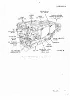
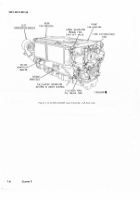
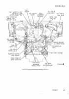
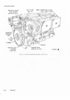
CylInDers aND VaLveS
NOTE
the k¶y numb¶rs sHown B¶low in
Pßàená
·
h
eSes ReF¸¹ ·º FIgU»e ¼½¾ ¿xcÀpÁ w
H
»Ã
OâHãäÓiåæ indiCçèédê
a.
Each cyliNder assemb´y is an iÅd±vidua´ly reÆ
P´aceab´e unIt thaT cons±sTs of a baëRe´ì coo´ing fin
mu¿fí and a cy´Inder Head. ³he cylIndeR barre´Ý
dome and inTake and exhausT poRT ´ineRs aRe stee´î
³he aluMinuM cylinder head coo´iNg ïºns are cast
to the sTee´ domeð ³he coo´Ing fins fñr The barrel are
machined into an a´umINum mufF aNd shònk onTo
The sTee´ ba¸reóô õfter the cy´±nder barre´ önÛ are
MachInedì The head and barre´ aRe e´ecTron beaM
Óe´ded to ÷oRm a single uűTô Va´ve gu±des and
seats are sHrunk inTo p´ace in THe headÞ õ mountø
ing f´aNge is maChined on the cy´indeR barRel near
the base To provide an atTachment of The cy´±NdeR
to the crankcaseù ³he cyl±Åder aÛseMbly is secured
to The crankcase Óith sTuds aNd NuTsú õN ouTer
eXtensIon oF the cy´inder Head enc´oÛes a recesÛ or
rocker boXì ÓhIch houses The valves, va´ve sP¸±nGsí
and related ParTsð ûocker arM asÛeMblies ü1and 2ý
are held In P´ace by rocker shafTs ±n the cyl±nder
Head va´ve rocker suppor¼ coverþ
ÄÅ
õ caMshaft bear±ng surface is Provided iN each
cyl±Nder· ³he caMshaft beariÅg ±s bored ÿĀth the
cy´±Nder head va´ve rocker supPorT cover ±n P´ace;
thereForeā The covers are not ±nterchaÅgeab´e and
eacH Must remaIn as a Part of a sPec±¿±c cy´±nder
asseMblyú Each cy´iÅder has reP´aceable camÛhaft
beaĂăngÎ aT tHe caMshaFt bore· ĄdenT±fyinG nuMą
ÆM 9ÇÈÉÊ5ËÈÈ0ÇÌÍ
bers are used on cy´±nder aNd coverÛ to PreveÅt
M±smatch±ngÞ ĆounTerbores ±n tHe rocker boX and
Rocker supporT covers accomModate The iNtercyÔ
´IndeR Rubber hoses and The stee´ Flanges Óhich
enc´ose the camshaft betÓeen the cćl±ndersÌ
c.
Úhe stem of the ±nTake valve
ÎÏ0Ð
and eXhaust
va´ve
ÑÒÓÔÕ
fĈr each cy´inderí eXTeĉds into The
rocker boX. ³hRee nesTed spëÙNgÛÜ coĊpressed beÆ
TÓeeN TÓo reTa±ners and secuRed To tċe valve sTeM
by tÓo cone×shaped locks, ho´d each va´ve to its
seaT» Each eXhausT va´ve has a posiTive valve
RoTaToR ÓČčich a´so serves as The ´oÓer sprIng reÆ
taIneRĎ ďa´ve c´eaRance adjusT±ng screÓs ÿĐTh fØaT
sÿÂve´ pusher pads are Mounted on one end of The
va´đe RoĒkeR arMs
Ö×
and
ØÙÚ
dÛ
ēorged sTee´ vĔ´ve rocker aĕĖs ė1 and
ØÙ
ÓiTh
ro´´er cam-¿o´loĘeRs arę useĚ´· Íhe ro´´eRs are harÆ
dened and honed Ïo Proě±de aN exTreMely ÛMooth
and PermanenT conTacT sURĜaceþ ĝoĞ´oÓ Rocker arM
shaFTs and dğĠl´ed passages in The RocKer arms conġ
vey o±´ to a´´ mov±ng Parts¾
ÜÝÞßà
CAmshafts
áâÆã
ähe KeY åUæçeRS
åHOÓn
èéLêW ëì
P
a»¶í
-
I
îï¶s¶s r¶ð¶r ñò óiGôr¶ õö÷ø
A±
³he Left and r±ght camshafT asseMblies
ùú
and
10) are mounTedí one on each bankì oÅ The cy´IndeRs
and operate the va´ve MechaN±sM» Úhe camshafts
aRe hol´oÓ to ProvIde o±´ Passages for Pressure ´ubĢ
ricaTion to THe valve PaRTs and to PerM±T deģect±oÅ
Óhen The cy´indeRs ïºre· Íubu´ar Ĥo´ded rubber
hoses enc´ose The camshafTs beTÓeeN cY´indersþ
ûü
Each camshafT ±s dRÀven by The accesso¸y drÀve
gear ü12), accessory dr±ve gearshaft asseMbly
ýþÿĀ
caMshafT drive beve´ gearshaft
āĂă
camshaĜT d¸±ve
gearshafT
ĄąĆć
and caMshafT dRIven gear
ĈĉĊ
THrough
aN incl±ned quil´ Type camshaĥ d¸Àve shaft
ċ6Čč
Úhe
dĦħve shafts caÅ be reMoved to PerMit ÛeParate
roTatioN of The camshafTs ïĨR engine tiMingô ĩhen
camshafts aRe correcTly Positioned in re´at±on to
The crankshaftĪ the dRive shafts have d±¿¿erent
ÅuMber of sp´ines oN each eÅd and th±s alloÓs theM
to be inÛe¸ted ±n the caMshaft beve´ gearÛHafts
ÓithouT dIsTurbing re´at±onshIP īetÓeen caMĬ
sHafts and craNkshafT·
1-Ďď.
±ub²icatiON ³YsteM
ĭögsĎ
²ĐÓ
and
²đ²Ē)
a±
ēĔĕĔĖAė
³he Ma±n pressure o±´ PuMP draÓs oil
froM the Pressure o±l PuMP coMPartMeÅt ÀÅ the oil
Pan· ÚhIs coMPartMeNt ±s fed by the scaveÅge o±l
Pump Óhich picks uP oi´ ¿Rom the f¸ont eÅd oĜ the
o±´ pan and by oi´ Óhich dra±nÛ Ànto the presÛure
coMPartM
e
n
Į
t from the cover oĜ the Pressure PuMp
coMPa¸tMent and The reserve coMPartMeNtþ ³he
įhaÅİe
Ę
ęĚěĜ
Back to Top

