TM-9-2815-220-34 - Page 31 of 532
b.
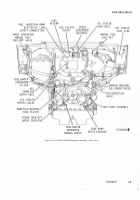
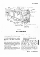
The EnginE featurEs a Fuel Injec±Ion system
and a ±UrbosUpErcharGED a²r ²nDuctIon system
wh²Ch oB±a²ns oP±²mum En³´nE µErfoRmanc.
¶h
E
·
fuEl InjEc±²on system has a FuEl ²nJEct²on me±er²nG
¸ump whIch supPlIes mEteReD Fuel to InDIv²Dual
cyl²nDErS ±hroUGh ¹ºel ²nJec±oR nozZlEs» ¶he fuEl
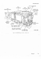
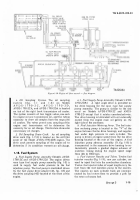
suµply p¼mp assEm½ly (¾¿GÀ 1-3) loca±ED a± thE ¾ront
of ±hE enG²nE Draws fuEL ±hrouGh ±he pR²maRy anD
sEconDaRy FuEL sys±Ems From thE VEh²cle fuEl tanks
anÁ DEl²\•Ers ²t to thE ²nJEc±Ion pUmpÂ
A
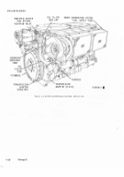
±urÃ
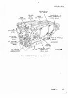
bosupERcharGer assEmbly (¾²GsÀ
1-±
anD
1²2)
²s loÃ
ca±ED On each s²DE oF the EnGÄne a± the REar. 'ÅhE
tÆrbÇsupErcharGErs arE ExhaustÈGas ÁÉÄÊEn anD
²ncrEasE ±he a²ËÌ ¾Íow prEssuRe EnteÎInG ±he a²r InÃ
±aKe man²FÏlDs (ÐÑGsÒ 1ÈÓ aND 1-2)Ô
I
c.
T
h
e
Model
AVDS-1790±2C and
modEL
² vDS³´ µ¶0·2C² engiNes ¸re
EquI¸¸ÕD w²Öh
¸
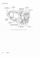
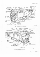
28¹ºo´t oiJ coo´ed dcgener¸toR (fIg. »¹1) c¸p¼blE of
650 ¸½per¾ ouTput o¿ER UÀe EngÁÂE opER¸TÃng
R¸ngÄÅ Æhe gEneR¸toR pRoduceÇ ¸n ¸´tEȸtÉÂg
cÊrËeNt
whIcH ²
Ç
×ØcÖIFÙØD wI±hIn ±hÚ
ÌnÃT To gÁ¿e ¸
diRect cÌÍEnT To t1Îe output teRÏin¸´ÇÐ
I
d³
Ûh
e
ÑoÒels
AÓD
S¹ÔÕ90-2Ö
²vDS¹lÕ90×2DØ ¸Âd ²ÓÙS¹ÚÕ90×2D²
E
ngi
n
e
¸Re equÃpped
wIth
¸ 28
ÊÜlÖ,
300 ¸ÏpeRe ¸iRÛcoo´ed
dÃÜect cÌÝentgeNER¸torÞfÃgÇÅ
ÝÈ5Þ
ÚßàÐl,¸Nd á·àâ8ãÅ
A
bloweR ½oToR ½ountEd on thE genEä¸toR dR¸ws
cooling
a²ß
FRo½ the cREw åo½p¸RtæEnt
Ö
hro
u
g
h
tHe ¸ÃÜ inT¸ke tubE wçècH exTendÇ ¸´ong the
cr¸NKc¸Çe Be´oW THE iNT¸Ke ½¸nIéoLd o THe rÃGêT
side oF tHE
ànáÄnâã
ëhe gEneR¸toR ¸iì eXh¸usí tube
Ä´bow
Iä
coînEcTEd to the Re¸R oé tHE EnginE
ÇhRoudï ðeneR¸toR outlet ¸iR iÇ EñH¸òÇtEd
åhæÜuçh
ÖhØ
rE¸r cooLÃng ón º¸ne.
e.
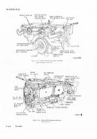
¶hE enènEs have a é4ÈÊol± solEno²D opErateD
s±arter (êGë 1-é)Ô
a
Low vol±aGE sens²nG moDule PReÃ
Êents star±eìí ac±Iva±²on Wîth ²mProPErly charGeD
battEr²Esã
f
¶hE EnGïnes are lubrIcatED by a fðrcED FeED
systEm. ñhE system cons²sts of ¾ouR c²Ròu²±s; ²Àeóô
±hE scaVEnGE c²RcuI±õ thE maIn or µREssURE o²l c²rö
cuItÞ the leveݲnG cIrcu²tô a÷øD thE make u¸ c²rcuI±ù
¶hEsE c²RcuI±s arE opErateD InDEpenDentLy by one
o²l pumP wh²ch cons²sts of FúuR sEpaRaûe sec±²onsó
g±
¶he ünýïnes aRþ EQu²PpeD ÿĀth two ²n±aKE
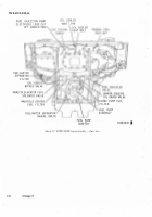
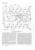
man²FoLD hEaters (FāGs» 1Ăă anD 㥹) whIch aRE ²nÃ
s±aLÝeD In thE a²R Intake sys±ems bEtween thE InÃ
take man²folD elBows anD thE ±urBosuPerchaRGĆrsć
¶hE heatErsõ whEn opErĈ±eDĉ pReheat ±he a²Î EnteRÃ
InG the cylInDers to facIÝItate colD Ċċa±hER staR±²nG
anD colD wEathEr IDLČ oPERatIonÂ
h´
¶hE Enčne cranKcasE ²s ÊEntED By an EnclosĎD
crankcasE bReďther system wh²ch ²s Êen±eD
±hRouGh thE cÉanKcasE bREather ±ubE ĐfÄGć 1đĒ) at
±hē leFt tuRbosu¸erchaRGeR eXhauĔt PIpeĕ
iµ
¶hE enG²nE Pr²maRy anD fuel/wa±Er seµaRa±oR
typE sEconDary FuEL ¾¿lteRs (êĖsė ĘęĚ anD
l
-ě) bo±h
ÛM
9¶·8¸5¹ºº0¶34
have toP mounteD blEEDeR ÊalÊEs
ôo
assIst ²n ±hE
REmoVal of a²r ¾rom ±he fuEl systemÀ ĜatEr Is rEĝ
movED au±oma±²cally By a constan± bLEeD or²fĞcE ²n
thE pr²mary FuEl ğltEr anD an au±oma±²c wa±Er
DraIn ²n ±hE fueLĠwatEr seParator ġĞL±ERĢ
»¼7½
Accessories
ģEfeR
±
o apPenD²X
a
for ²nFðrma±²on on enG²nE acĝ
cessoĤEsÂ
»¾¿À
CRank±²se
¶hE cRanKcasE (¾¿GĢ
±Á1)
²s a onEĥP²Ece alumInum
castInG w²th foRGEÁ alumInum ma²n bEar²nG caµsć
¶he bEaR²nG caps functIon as an IntEGral part oF
±he cranKcaseć Ħach
õ¸p
²s securED on stuDs ħĨĩh
four slo±±ED nu±sĪ īÅwo thRouGh bðl±s clamp thE
maIn beaĬ²nG caP ²n ±he ±unnEL slo± of the cranKĭ
ĮasEį İIıh IJh²s ±YPE of crankcasE anD bEar²nG cap
cons±Ruct²onij unIfúRm loaD D²stRIbutIon In the bearĴ
²nG arEa ²s obta²nED maK²nG µoss²blE un²ġðRm D²sĴ
±r²but²on of combus±²on ¾orcEs ovEr thE ent²RE
cRankcaseĵ
» ÂÃÄ
MaiN Bea³I´gs
ĶhE seķEn rePlacEablE ma²n bear²nGs aRe thE
s±eelĸbackEDõ sPlIt typE, haÊInG co¸Per-lEaD alLoy
bEaRInG surfacesã ¶he cEntER ma²n bEarInG Is
DouBlEĹ¾ĺanĻED w²th bEar²nG ma±eļ²al ±o control
crankshaft EnD play anD thRustĽ
»ÅÆÇÈ
CRaNKshaft, FlywhEEL, and DampEµ
NOtE
'öe key nu½bERÇ s÷own bEloø
²n
p¸ùeÂú
I
tHEseÇ REF ER to éûguRe 1±8ü
C²
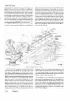
ľĿían ks haFt assEmbLy ĐŀŁł Is a nItŃńĞDED s±eEL
forg²nG w²±h seķen ma²n bear²nG JoUrnaŅs anD s²X
crankp²nsņ Ħach cRanKp²n accommoDa±Es two oµŇ
posInG connect²nG RoD assEmbl²Es (ŀ6)Â ňlanGEs aRE
ProVIDED on ±he crankshaF± FoR mountInG thE
ʼnywheel (Ŋě) on ±he rEar enD anD a ŋors²onal ʲbRaĴ
t²on DampER Ō<ōŎ) on ±hE Fļont enDŏ
BÉ ÊJJ
c
r
N
kp
²n
ýe¸þÿng jouĀ¸´s ¸Re Holloø to
āEduce øeÃgHTÐ Ăo´eÇ ¸re drÃlLed døgo¸´lY THroÌgH
e¸ch ½¸in ýe¸RiNg ăouĄ¸´ ¸nd eñteÂd through tHe
cR¸Âk ąheek
¸nd crankpÃn to pRo¿ide ¸ direcĆ
p¸ÇǸgE
fr
oil under pReÇÇuRe
±o Öh
E connEcting
rod ¸Nd cr¸NKÇH¸éT
maIŐ
ýe¸RÃćĈgs ¸s ÇHoøN ÃN
éÁgòre 1ĉ¶Ċ
c±
ÛőE cRanKshaf± anD FlywhEEÝ aRe statIcally anD
Dynam²calÍy balanceDÀ
DË
¶hE torsIonal ÊIbra±Ion Dam¸ER ŒŀœŔ ²s a prEc²Ã
s²on ʲscous ±yPE anD ²s replacEablE onLy as an
assemblyĢ
»¾Æ»À
Connect¶´g ·ods aNd B¸aRi´gs
¶he connecÖInG roD asŕEmbĺIes Đŀ6, FIGÒ 1-8ł are taŖ
pEreDô ŗÈbeam sect²on steel forŘînGsĢ
a
bronřEŚ
śŜAnŝE
Ì
ÍÎÍÍ
Back to Top

