TM-9-2815-220-34 - Page 367 of 532
TM 9-2815±220²34
Section
XV. REPAIR OF CAmSHAFt AND ASSOCiAteD PARtS
³´µ
General
a.
This section covers the repaIr of the camshafts
and
assOIated parts. SpeciFic instRuctions on
disassembly, cLeaning± InsPction² and assemBLy
accompany the repair operatIons. ³epaIr stand-
ards of individUaL components foLLow the InspEc´
tIon prOedUreµ StUd identIfIcation InformatIon Is
incLUded iN the repaIr pr¶edUres·
b·
³epair of ¸Ight and Left camsha¹ºs Is sImiLarµ
»or instrUctional pUrposes repair procedUres ¼r
¸n¹ crº»YL¼nd½r
SL(EVe FlA±G£
lIfT²³´C eYµ
r¸Gh¾
cAMsHA¶t
the rIght
camshaft
W½LL Be g¾ven ¿¾tH refeÀences to
tHe
le¹Á camshaFt oÂLY
wHere repair
ÃroceDÄres
varÅÆ
¿À ÁÂÃÄ DÅsassÆÇBly
a.
³emove LiFÁIÇg ÈÅe (Ég· 3Ê256)Ë preÌormed hose
and intercÅlÍÇÎÈr hose
flangE, and SeparaTe
the
LIFting
eye anÏ
f±anGe
From
Hose.
1·/ER.¸yliNO¹r sº»¼v½
PRE¾oRMµD hO¿À
pÁÀÂoR ¹O
ÃAcÄWÅg
f ÈÉÊ Ë
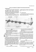
Fig,J.fSI± Rrmovi7O²in1tU³nG l´µT¶nG eVE· iN¸¹²CLº»Nd¹¼b½¹j¾oNGu¿oNd hO1ÀÁÂ
mo t AVDS·l790±$C ²1d Av³s´L79µ´¶³
EÃq³nÀÄ
ÌoÍÎ
ModeL
Ï
VÐSÊ179Ê2ÐÑ engÒnes are not
eqUipped with LiftIng eyes at cyLinder Óos·
Ô³ and
ÐÑÒ
ÕntercyLinder hose Ö×angEs are
Used at these lØcatIons·
bÓ
Ñemove foUr g¸oUps of IntercylInde¸ hose
Ùanges and pÚeformed hoses and separate the
ÙanGs fÛom the hoses·
I
c¸
Remove two hose claMps (34, fig. 3-258) And
Ü
H
e
ÝÞBBßà
Hose ±33) fro²
¹º
á
s
H
a
Ô
t
Ïâ¾ve
s³AFT
fLangE ´3µ)
ÕÖ
Ñemove foUr selfÊl¶kIng nUts
(30,
ãg.
2ä8å
and æat washers ç2èå and remove camshaft d¸Ive
bevel gea¸éhaft adapêer ç3èå and assOIated pa¸ês
as an assemBëy from camshaì gEar hoUsIng ç42åí
e»
³emove and dIscard preÌØrmed packIng ç4îå
f¸om Bevel gearshaft adapter
(3×)
and remove and
discard preformed packing
ØÙÚ
ïom oiL transfer
tUbe in Bevel gea¸shað adapter· ³emove two Bolts
ÛÜ6ÝÞ
lockwaAhe¸é
ßàáâ
and ñat w!hers ç37å and
ÚEmove Camshaò dÚóveshafê aôapêEr ç32å õ¸om
bEveL gEö¸shað adapter ç3èå· ³emove and dIsCard
÷sKet
ãäåæ
Ìoçè
Õt wóll bE necessa¸y to move the camshafê
drIve gear a way ¹roø the camshaù driven
gear to gain
CLearan²e
for reøovaL of cam´
shaft asseáúLYû
é
ReMove ³amsHa´µ
ê7ë
beVeL gear
(ü)ý and gEar
cover
ìíî
as an assemBlÅ from gear
¶ousIng
ç42å·
Ñemove camshaft dÀóve bevel gÈarshaþ (1å from
gear hoÄsing.
g¼
ÿLace
a··emBLeD
camsha¹º In a softĀjawed vise
and cUt JockIng Wāre and remove eIght áachine
boLts (Ăå and camshaft cover (5å± and Bevel gÈar çüå·
ïð
ÿLace assemBLed throttle
¸On¹ºoL
cross shaFt
ă2Ąą Ćg· 3ć25Ĉå
in
a so¹ºćĉawed vIse and remove camĊ
shaft end cover pLate (22å from bċLL bearIng
ñòó
By
carefUČLy tappIng on end of plate čĎth a ďoft hamĐ
mer·
Ìôõè
đhe Left camshafÁ does not have a cover
pĒate asseáBLŵ
ö÷
ēUt
Lo»k¼ng
w¾r
e
and remove
øuù
capsĔrĕws
çîü, figĖ3Ê258å and flat washers ç17å· ³emove
tachomeėĘÚ dęve adapter ç18å f¸om end pLate (20å
and remove and ÏIscard prefØrmed packIng
úû6Ýü
Ñemove oIĒ éeaL (îĈåĚ
ě·1· ĜUt LOkIng ¿ĝre and remove foUr capĞcrewğ
ĠġĢnģĤ
ý
3þÿĀ5
Back to Top


