TM-9-2815-220-34 - Page 371 of 532
TM 9·2815-±±0²34
7'able
8-2(.
CAmsLw/I ±1²d D1i³´cS REµ1a¶r ·t±n¸¹º»
-
ContiNued
FIg.
Ref±
Poi²T O³
Si´Es
and
µ¶Ts
WEar
c·mpO¸e¹º
»·±
le¼½er
MeA¾U¿EÀÁNÂ
oÃ
new
ÄÅÆÂs
LiÀÇÈs
3-2±1
w±r
Éit oÊ lOwe1Ë Ì¿ÍN¾ÄÎug ÏN qÐÏÎÎÑ
0.0²³2L
0´µ025l
0¶00·0¸
¹º»¼8
cÍmÒhAÓÂ EÔ
d pl
a
t
e
¹º2¼8
Õ
Ö×ÂsØdE dÏamE½eÙ O³ oil sealÚ
½¾¼¿½µ
1²505³
.
¹º2À8
²
ÛNÜide dÏaMeÝeÞ
of
ßaM¾Hųà
½¶499µ
)ÁÂ0µ0
•
End ÄáAâe.
¹-2¼8
N·p
ãÏà o³ OÇÎ sEAÎ Çä påaÂe boæEç
OÃoÄ!ÅT
Æǵµ6ÈT
•
Reèé¿ Âo êë¿ag¿ÅìH
3´µ7c foR expLAnation oF symbo¶s¸
TaBl¼
¹º»¼½
½a¾1²S¿ÀÁf D¾iv HouSÃNg ÄÅUÆ ÇÆÈɲŶFÊËÌÍÎOÏÐ
íig±
îe³ï
Seðtϲg
»
o
¾
ñoò
óeôGHõ
¹ÉÊÀ8
27
½Ë̹2
3-104.
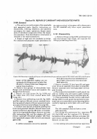
Assembly
a.
InstalL bearing (21, fig. 3-258) and oil seal (19) in
camshaft eNd Cover plate (20)± INstall a New
PRefOrmed Pack²Ng (³5) On tach´meTer dr²Ve
adaPter (³µ) aNd seCure dr²Ve adaPTer On coVeR
Plate W¶th four CaPsCrews (·6) and f¸at washers
(17)¹ Secure caPsCRews º»th lockiNg ¼½re¾
¾¿ ÀÁ
¿nstal¸
new
gasket (45À
f²gÁ
3Â25µ)
and
tachometer dÃÄve Cover (ÅÅ) on Camshaft eNd CoVer
suPPorÆ (20) aNd secure w²th four fÇaT washers (17)
and caPscrews (³6)¾ InstaLl loCking wireÈ
NOtE
Éhe Çeft camshaft dOes NOT haÊe a cOver
plate assemblyË
b.
ÌlaCe
right Camshaft (7, FigÍ
3Î258)
in a
softÂjawed V²se and ²NsTall bevel gear (6) and
camshaft cover (5)Ï
Ðecure cOver and gear
tO
camshaft with eight mAChine Bolts (Å) and seCure
boÑTs with lOCk²Ng wireÒ
CÂ
InstalL camshaFt dr²ve beVeÑ gearshafT (1) and
assembled camshaft (Ó) in gear housing (Å2)Ô
no³e
It wilL Be neCessaÕÖy tO mOve the BeVel
»o.
æeQ'D
Stö÷ ¾Ïze Íød ÎeùgTú
8
3Í8Î½Ï (ÐÑÐ6Ò
x
3Í8Ó2ÔÕ Ö1¹/Ð6×
X
ÐÓÐÑÐØ
gearshaft away fRom the camshaft dr²ve
gear to gain ClearaNce For insta¸latiOn Of
×amshafØ asÙemBly±
cl´
Using a new gasket(38) instalÚ Camshaft driVe
shafT adaPter (32)
ÃÄÅ
ÛeVel gearshaft adaPter (39)
and seCure ÜÝth twO bolts (35) loCk washers (36) and
fÇat washers (37)¹ ¿Þstaßl a New Preàármed paâking
(2µ) oN Oil traNsfer Tube in bevel gears haft adaPTer
aNd a new Preãrmed PaCking (Åä) on beVel gearå
shaft adaPterÈ
EÆ
INstalL assemæled beVel gearshafT adaPteR (39)
on camshaft gear housing(ç2) and secure with four
sèlFloCking nuté (3ê) and ëÚat washers (2ì)Ô
l
[nstall hose (33) ON camshaft drive shaft adaPtÂ
,
eí aîD
SÇÈuÉÊ
wiïh twð hñsE òlamós
(±²)³
gË
Ìosition two iNtercylinder hOse fLanges (figô
3õ256) oN eaCh Of Föur PreFörmed hoses and ²Nsta¸÷
hOse assemBLies on camshaftø
hµ
Ìos²tion lifTing eYe and remaining interCYlinù
der hose úûange ON remaiN²ng PreëOrmed hOse aNd
install hOse assüýmBlþ ON camshaftÿ¾
Section
XVI
REPAIR OF THRO±LE CONTROL CROSS SHAFT,
MA²UAL fUEL ShuTOfF ROD³ AND ASSOCIA´µD PARTS
3´µ05
Ge¶era·
Āh²s seCt²oN COveRs the rePair Of the thrOttle cOnā
TROl
CRoss
shaftĂ
fuel
²nJeCtiON
PumP
ă²Nkage,
manuaĄ FueL shutoFf rod, aNd assoCiated ParTsø
SPeCiFic instructiOns
On disassemBlY,
cleaniNg,
insPeCTioN, and assemblY acComPany the RePair
OPerations¾ ąePair standardĆ oF ²Nd²v²dua¸ COmPOć
neNts fĈllow the insPeCt²on pRoCeduĉĊeÏ
3-106·
D¸s¹ssemb·y
ÌÍ
ċlaCe the assemb¸ed throttle CoNtrol crOss
shaft and Fuel inJeCTion PumP linkage ²N a sOftā
jawed Vise and remOve CamshaFT eNd PLaČe ba¸l
bearing retaining ring (Å5Ă Figč 3Â259)Ď ďsiNg a suitĐ
abLe PuLler, đemove Ēamshaft end Plate balL bearć
ing (23)ē
b.
ąemoVe camshaft end Plate BeariNg inner reć
Ta²n²Ng r²Ng (Å6)Ô ąemoVe caP screw (2Å) and
loCkwasher (25) aNd remove thrOttle leveR assemĔ
bLþ (ç7) and woodrufF keþ (ç8) ĕrom thRottle CONtrol
CrOss shaFT (26)Ė
CÂ
ąemOVe CRoss shaft BraCket beariNg RetaiNing
ring (33) and using a suitable Pul¸er, remOve throtć
TLe coNTROl crOss sh aft brackeT (35), bearing (5ė) and
ReTaining r²ngs (3ç) as an assembăyË ąemOve ²nneR
crOss shafT BRacket beaĘ"²ng retain²ng ring (33)
fROm crOss shafT±
d¸
ąemoVe CrOss shaFT leVer bearing ęeTaining
ĚhěNGĜ
3
¹º»¼½
Back to Top


