TM-9-2815-220-34 - Page 377 of 532
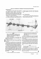
Jar balL bearing retaIning ring (22). UsIng a suIt-
abLe p±lLer, remove caMshaft end plaTe annular
baLL bearing (23)² Remove Inner annular baLL
bearing reTaining ring (22)³
b.
ReMove capscrew (24) and lockwasHer (25)´
Reµove THroTTle lever assembly (26) and Wood
r·F¸ key (16) ¸¹oM TºroTTLe control straIgHt sHaft
(»7).
c.
ReMove ouTer retaInIng ring(27), ¼laT wasHer
(28) and Manual ¸½el shuTofF lever (29)² ReMove
inner FlaT wasHer (28) and inner reTaIning ¾¿ing
(27)À ÁeMove Two plain seals (30) and two sleeve
bearings (31) ¸¹oM conTrol lever (32)Â
d±
ReMove capscrew (20), LockwasHer (»9)Ã conÄ
trol lever (»8)Å WoodÆFF key (15)Ç Two flat wasHers
(49)Ç and tHroTTle conTrol Lever LEÈk (50) ¸¹om
ThroTTLe conTrol sTÉ'ÊigHt sHafT (17)³
e±
Ëoosen Hexagon plain nut (52) and remove
macÌine screw (53) and angle brackeT (5») from
reÍote conTroL Lever (47)Î Remove retaining ¹Ing
(4Ï)Ð UsIng a suItabLe puLLerÅ remove remoTe control
Lever (47), two annuÑar baLL beaÒIngS (45), and two
retaInIng ÓÔngs (46)
as
an
asseMblyÕ
Remove
annuLar baLl bearingS (45) and retaIning rings (46)
f¹oµ reMoTe control lever (47)Õ
Ö× ReMove two capscrews (»)Ç lockwasºers (2)Ç and
reµove elecTrical soLenoId (3), By
disengagØng
)
solenoid link (8) f¹om eye on inner solenoid conTroL
Housing (Ù0). Remove and discard gaskeT (4) and
coTter pin (9)À ReMove Headed sTraigHT pin (Ú),
solenoId link (8), coMpressIon sp¹Øng helical re
Tainer (6)Û and coMpression HeLiCaL spring (5) ÜÝom
elecTrical solenoÞd (3)ß
g²
ReMove THree capscrews (34), LockwasHers
(35)Ç FlaT wasHers (36)Ç and access cover (3Ú) ¼roM
ouTer solenoid control Housing (4»)à ReMove and
dIscard gaskeT (3Ï).
h²
Ëoosen heXagon plaIn nut (44) and reMove
Machine screw (43) ¸rom Ináâer soLenoid controL
hoãsing (1ä). Remove outer reTaInIng rIng (14)
anD fLat wasHer (»3) from throttLe conTrol
straIghT shaft (»7)å æLide shaft thro±gH inner and
outer solenoid controL HousIngs untIL ann±lar
baLL bearing (4ä) and retaIning rings (39) are eXç
posedÐ ReMove outer retainIng ÒIng (39)Õ Using a
suitabLe puLlerÇ remove ann±lar ball bearing (4ä).
Reµove inner reTaInIng rIng (39). æeparate Inner
anD ouTer solenoId control housIngs and reMove
outer solenoid conTrol Housing (41) and encased
plain seaL (42) FroM sHaftÀ ReMove encased plaIn
seaL (42) ¸roM ouTer solenoid control HousIng (41)À
Reµove inner retaining ¹Ing(»4), flaT wasHer (»3)Å
and inneèé
solenoId
control
housing (»ä)Å witH
TM 9-2815³220´34
insTaLLed needLe roLler bearIngs (Ȑ), and encased
pLain seal (»2), froM throttLe controë sTraIgHT shaft
(»7)ß
Remove
needle rolLer
beaìIngs (»»)
and
encased plaIn seaL (»2) f¹oM inner íoLenoId conTrol
Ho±sing (»ä)À
i. O±lctCd
j²
RemovE two hosE clamps (2, f
i
g
Õ
3-259.2) and
dusT aND
moiSturE
sEal
booT (3) Fom yiCldaBl±
²oN tro³ rod assEmBLY ´6)µ ¶oosEN HExagoN PlaIN
Nut
(I
I)
aNq
rEmovE
rig·t HaNd roD End ¸la¹N
BearºNg
´10)
»rom
govE¼or
½on¾rol
îOd
(12)µ
¿oosen ÀEXagoN Álain nu (23) aÃD rEmovE leÄt
hanD roD ENÅl PlaiN BEariÆg (24)
Çrom govErNor
coNTrol roD È 12 )
À
kµ
REmovE
ÉEÊAgon
HEaD
caËs½rEw (9)Ì aND
lo½kwasHÍÎ (8)Ï REmovE BElÐ ÑraNK (7) anD WooDÒ
ÎuÓÄ
KeY
´22) Órom straigHT sHaÄt (13)Ô ÕEmovE two
ÎETainÖng rºNgs (×Ø)Ù REmovE rotatÖNg EYE BrAÚkEt
(×8)Û two ÎEplA½EmENT BEAriNg sÉiÜÐds (1ÝÞ, two
ANNUÐaÎ ßaÐl ßEArºNgà (×6)á ANd two âEtAãnºng ängs
(×å)
ÄÎom
sTÎæºgçT
shAÄt (×3)è as
AN AsàEmBÐyÔ
REmovE two
¹ïpLAcïµïnð
ßEAÎéêg sÐëiEÐds (×5), Two
ANNìÐAr ßALÐ ßEAÎiNgs (×í)î ANd Two ÎEtaïNºNg κNgs
(×ð) ÄÎom âotAtºNg EYE ßÎAcñEt (×8)Ô
NOTE
òhE rod
b
Car
i
N
011
tHó YºEldaBlE ½oNô
TroÐ rod AssEmBly æÎE piNNEd and AÎE NoT
to BE dºsassEmBlEdõ
¶·¸¹º»¶¼
³Lean´ng
Refer to paragrapH 3ñ3òó
¶½¾¿º»ÀÁ
µnspe¶T·on anD RePa¸r
Re¸er To parag¾ôapHs 3ñ3Ú and 3õ38 for procedure
and Tables 3ö2ÏÕ1 and 3ö28.2 For repair sTandards÷
¶½¸¿º»ÂÁ
Assemb¹y
a.
ønsTall Two sleeve bearings (31Ç ¸igå 3ö259à»)Ç one
in eacH end oF control lever (32)à ùeaúÔngí must be
insTalLed äÕ25ä incH below end s±r¸ace o¸ Lever.
ReaM bearIngs to a dIaMeTer of ä²627ä û ä²629ä
Inch, after instalLation. üLean Lever afýer beaÒIngS
are reamed, beþre seaLs are InstalLedÕ ÿnstaLL two
pLaIn seals (3ä)Ç one In eacH end o¸ controL Lever (32)Ð
ĀIp of seal M±st be To outsIdeà æeaL Must be ān
sTaLled ¼Ăush or below end s±r¸ace of Leverà
BÃ
önsTAÐl two ÎETAºNºNg rºn
(1åè
fgÄ
3÷2øùõ2)
aNd Two a
n
n
u
lA
r
bALl
BúaÎÖNgs (û6) in rotatiNg EyE
BrA½kET
(I
8)ü ýnstaÐl straigþt sçaÄT (13) Ön
Assemÿ
ßled ÎoTaTing ĀYE BrA½ñEt and sE½āÎE wÖtÉ
two
ÎEĂla½EmEnT ăearºNg sĄiElds
º»
5) ANd Two
rETaÖNô
ing riNgs È14)Ô öNsąall ĆooDrāfÄ ñeY (22)
anD
BEÐÐ
½raNñ ćð) oN sTraigHt sĈaÓt (×3)Ô ĉĊsTaÐl cæ¸s½rew(ċ)
ăd
ÐocñwasÉČr (8)
in
BEÐl ½raNñč
C
h
AN
G
E
Å
ÆÇ165
Back to Top


