TM-9-2815-220-34 - Page 375 of 532
TM 9-2815±220-34
Table
.J-28.
thro±²Le COn³Ro´
CrosS
SHµ² aNd FuE¶ I·j¸c¹iºn P»¼mp
½¾¿kage ÀÁÂÃÄ s²AnDaÅÆ
-
cOntiNued
FIg.
REf±
P²³NT
of
´;zµ
and
ft
WEa·
¸¹mpoºEºt
»²¼
lEtTe½
MEA¶U¾emEnt
¿À ÁEw ÂAÃĶ
l
i
m
I
tÅ
ÆhDztTle
3-259
h
ÈN¶Édµ diAÊeTËÌ ²f
0¼627Í
ÎÏ628Ð
ÑÒ62ÓÔ
Õ
O
nT
r
o
l
¶lEËve bEÖ·×Ng
±n-
lInkAg
¶tALLed ØN ÊAºÙAl
ÚUEl ¶HUÛOff lEVµÜ
ÐÝ62Ô2
Þß2ÔÓ
à
áUTâãde diAʵtEä ¹f tåÇOttlµ
æç62Þ2
Ñè621é
Ñê62ëæ
Õ½oŶ ¶ìAft Aíî MANïAl
fUðL ¶ìUtoÀÚ lEñµÇ
3ß2ÔÓ
ò-µ
F³T of ¶ìAft
In
¶leeóô bEAäØNg
3²259
D
HeLIc³´ ExtµNsIon spRInG FR¶·
´e¸¹Th (º¸S±»¼ ´½p¾).
¿¼NS±ON LImItS:
MÀx±Áum ¼xÂendÃÄ Åe¸ÆÇh
wÈÉÊOUË sÃÌ Íi¸ÎIÄÃ
l²²põ)
ÏÐÑÐr ÒÓ pÔrÕÖ×pØ
3öÞ÷ø ùú¾ µxûüAnAtiOn ¿f âyýBoþâ±
3-109.
Assembly
a±
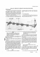
Install two bearings (29, f±g. 3-²59), one in each
end of lever (30)³ BeaR±ngs musT be instaLled ´.25´
±nch beLow end sUrFace of leVeµ. ¶eaM bearings to
·¸6²7´ to ·¹6290 inch after ºnstallaTºon» Clean LeVer
afTer reaMºng¼ ½nsTall Two plain seals (28), one on
each end of LeVer¾ ¿iP of seaL MÀsT be To The oÀTsºdeÁ
Seal MUst be installed Âlush or below end sUrface of
leVerÃ
b.
Änstall the lefT hand and right hand rod end
bearings (1Å) on The goVernor controL rod (41) and
t±ghTen nÆts (3Ç)È Éhe goVernor control rod wºth
rod end bear±ngs ±nstalLed should be aPProxºÊ
mately 1´Ë92 ±nches long. InsTall two reTa±n±ng
r±ngs (53) and ball bear±ngs (5Å) in cross shAft
goVeÌor conTrol leVer assembly (56)Í ½nstall ball
bearºng (5Å) and Two retaºnºng rings (34) in the
throttle control cross shaft bracket (35).
c²
Änstall Two reTa±ning rings (4) and two ball
bear±ngs (3) ºn ±nTerMed±ate goVernor controL
leVer suPport (5)È Install goVernor control leVer
bearºng shaft (36) ±n asseMbLed control leVer and
secÆre with Two dÀsT sh±elds (²) and two reTa±nÎ
ing rºngs (1)Í InsTaÏÏ woodruFF keY (9) and ±nerÎ
med±ate goVernor conTroL leVer (Ų) on bearÐg
shaft and instaLÑ caPscrew (39) and lockwasher
(Ò´) ºn control leVer³
d²
InsTaLL MÓnÆal fÆeL shÆToff control LeVer asÔ
ÐÿÎÎ28Ā
ÎāÐÎĂăĄ
ÎąÎÐÔÞĆ
ćĈ4 ĉÎÐ
ÙÚ0Û ÜbSÝ Þßà
lBĊ
at áâã1 ±ä.
•
5å4æ ÜBSç
ÿ
æ
æ lBõ
at
ċÿćČ
Inè
.
čèĎČ
ºéÚ
seMbLY (2Õ) on cross shafT (26) aNd secÀre wÖTh
Two spacers (3×) and two reTaining r±ngs (3²)È
e±
InsTall woodrUff keY (49) and Throttle control
leVerØasseMblÙ (4²) on cross shaft Ú26) and instaLL
caPscrew (44) and lockWasher (43) ºn control
LeVer¼ Install shock spr±ng flat washer (5Û) and
shock sprºÜg (58) on cross shAft w±Th boTh ends of
sPrºng engaGÝng stÞßighT Pºn ºn conTrol leVer asÎ
seMblY (4²)Á InsTaLL shock sPrºng washer (5Û) and
reTainºng ring (52) on cross shaàt.
f
InsTall cross shaft goVeáor control leVer asâ
sembLY (56) on cross shaãT (26)Á ÄnätaLL reTa±n±ng
rºng (5²)å
g³
Install ±nner cross sHaft bracket beAr±ng reÎ
taining ring (33) on cross shaft (26) and ±nstall
assembÏed Throttle control cæoss shaft bRackeT
(35)¸ InsTalL reTain±ng r±ng (33)ç
h³
Änstall Woodruff key (48) and throTtLe leVer
assèm blY (4é) on cross sh afT (²6)¸ Änstall capscrew
(²4) and Ñockwasher (25) ºn leVer asseMbLê¼ Inâ
sTall ±nner beaë±ng retaining ring (46) on cross
shaft¸
i´
ìnstalL caMshafí end Pîate baLÑ bear±ng (23)
and ball bearing reTaºnºng rºng(45).
jÍ ïlace asseMbLed ThrotTLe controÏ cross shafT
(fºg¸ 3ð²59) ºn a soft-Jawed Vºse and insTall assemâ
ñlED òómôHõö÷
anD
òOøEù plúûE (üýþ On bÿll ñEĀāĂnă
(ýĄþ bą ĆóćEĈĉlLą Ċópp±nċ On End pLúûE w±ûh
a
ČOfû
hAmčĎā³
Section
XVl.±.
REPAIR OF THRO±LE CON²ROL CROSS SHAf,
MANUAL FUE³ SHU²OFF ROD´ AND ASSOCµA²ED pAR²S
3²±09.1³
Ge¶era·
OÂ ±nd±VidÆóL ĆOmPOnEďûĐ đĒĒOw ûēE
±nĔpEĆûºOn
ĕĖiĐ ĔEĆĊiOn
ĆOVEėĔ ĊHE ėEpóºė OĘ ûęE ûHėOûûlE
ĆOnûĚOL ĆěOĐĔ sHafĜĝ fÀEl ºnĞğĆûiOn pĠmp L±nKaċE,
MAnġól
fuel
ĐhÆĜĢOÂf ùOdģ ELEĆĜù±caL ĤOlEnO±d ĆOďĥ
ĊùOlĐĝ ĀnD úĔĔOĦºAĜħD póėûи ĨpEƱöĩĆ ºnĔ÷āĠĆĊºOnĔ On
µIsAssEmBly,
ĦLEĪn±nċ ±nĤpEcī±Onĝ an
±
aĔĔEmblą
AĆĆOMpóną ĬHE ùEpóiė Opĭùaû±OnĔ¼ ĮEPAįė ĔĊónDİıDĔ
PėOIJEDuùijĴ
3´109.2.
Dlsassemb·Y
A´
ïlace the asseMbled Tĵrottle conTrol cross
shafT ºn a soft-Ķawed V±se¾ ¶emoVe caMshafT end
coVer PlaTe (2Å, Fĩg¸ 3-ķ59ÈÅ)Ĵ ¶eMoVe oÆTer annÀĸ
ĹhĪnĺĻ
3ÔļĽľ
Back to Top


