TM-9-2815-225-34-P - Page 190 of 736
TM 9-2815-225-34&P
0018 00
0018 00-4
PISTONS, CONNECTING RODS, AND BEARINGS (Contd)
CLEANING AND INSPECTION
1.
For general parts cleaning information, refer to CLEANING, WP 0051 00.
2.
For general parts inspection information, refer to INSPECTION, WP 0051 00.
NOTE
Replace any part that does not pass visual inspection or is
outside specified wear limits.
3.
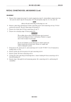
Inspect piston (1) for cracks, breaks, scores, galling, or scratches. Remove small scratches with
crocus cloth.
4.
Inspect piston ring grooves (2) for cracks, breaks, missing sections, and galling.
NOTE
There are two different ways to inspect piston ring groove
clearance. Either method is acceptable. If using piston ring
groove gauge, perform step 5. If piston ring groove gauge is
not available, perform step 6.
5.
Using piston ring groove gauge, measure piston ring groove (2). Discard piston (1) if piston ring
groove gauge widest shoulder comes in contact with piston (1).
6.
Position a new piston ring (3) in piston ring groove (2). Using a feeler gauge, check the clearance
between piston ring (3) and piston ring groove (2). Replace piston (1) if clearance is more than
0.006 in. (0.15 mm).
NOTE
Ensure temperature is 70°–90° F (21°–32° C), or false
readings may be taken.
7.
Using micrometer or equivalent, measure piston outside diameter at point A, 1.0 in. (25.4 mm)
below piston ring groove (2). Piston outside diameter at point A should be 5.477–5.480 in.
(13.912–13.919 cm). Replace piston (1) if worn beyond specifications.
8.
Using micrometer or equivalent, measure piston skirt outside diameter at point B, 1.0 in.
(25.4 mm) above bottom of piston (1). Piston outside diameter at point B should be 5.489–5.493
in. (13.942–13.952 cm). Replace piston (1) if worn beyond specifications.
NOTE
Ensure temperature is 70°–90° F (21°–32° C). At 70° F
(21° C), add 0.0005 in. (0.013 mm) for every 10° F (12° C)
up to 90° F (32° C), or false readings may result.
9.
Using inside micrometer, measure piston pin bore at point C. Piston pin bore should be
1.9985–1.9990 in. (5.076–5.078 cm). Replace piston (1) if piston pin bore is above 2.0000 in.
(5.080 cm).
10.
Using micrometer or equivalent, measure piston pin (5) outside diameter. Piston pin (5) should
be 1.9988–1.9990 in. (5.0769–5.0775 cm). Replace piston pin (5) if outside diameter is out of
round more than 0.001 in. (0.025 mm).
11.
Inspect dowel pins (4) for cracks, chips, and bends.
12.
Using micrometer, measure outside diameter of two dowel pins (4). Dowel pins (4) should be
0.220–0.250 in. (5.59–6.35 mm). Replace dowel pins (4) if not within specifications.
Back to Top


