TM-9-2815-225-34-P - Page 208 of 736
TM 9-2815-225-34&P
0020 00
0020 00-2
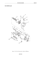
ROCKER LEVERS AND ROCKER LEVER HOUSING (Contd)
DISASSEMBLY
1.
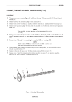
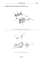
Remove two exhaust rocker lever adjusting screws (3) and nuts (4) from exhaust rocker levers (2).
2.
Remove two injector rocker lever adjusting screws (8) and nuts (9) from injector rocker levers (7).
3.
Remove two intake rocker lever adjusting screws (12) and nuts (13) from intake rocker levers (11).
4.
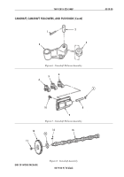
Remove setscrew (14) from rocker lever shaft (16) and rocker arm housing (15).
NOTE
Tag all rocker levers before disassembly to aid in assembly.
5.
Using press and mandrel, remove rocker lever shaft (16), two exhaust rocker levers (2), injector
rocker levers (7), and intake rocker levers (11) from rocker lever housing (15).
6.
Remove two plugs (18) and O-rings (17) from each end of rocker lever shaft (16). Discard O-rings
(17) and expansion plugs (18).
7.
Using press and rocker lever block and mandrel set, remove two bushings (1) from exhaust rocker
levers (2). Discard bushings (1).
8.
Using press and rocker lever block and mandrel set, remove two bushings (5) from injector rocker
levers (7). Discard bushings (5).
9.
Remove two ball socket seats (6) from injector rocker levers (7). Discard ball socket seats (6).
10.
Using press and rocker lever block and mandrel set, remove two bushings (10) from intake rocker
levers (11). Discard bushings (10).
11.
Repeat steps 1 through 10 for remaining two rocker lever housings.
CLEANING AND INSPECTION
1.
For general parts cleaning information, refer to CLEANING, WP 0051 00.
2.
For general parts inspection information, refer to INSPECTION, WP 0051 00.
NOTE
Replace any part that does not pass visual inspection or is
outside specified wear limits.
3.
Inspect rocker lever housing (15) for cracks, breaks, chips, elongated or stripped bolt holes. Repair
any damaged bolt holes.
4.
Inspect rocker lever housing (15) breather vent hole and oil passages for blockage and obstructions.
Clean out breather vent hole and oil passages if obstructed.
5.
Inspect rocker lever housing (15) shaft bore, for sharp edges, nicks, or burrs. Rocker lever housing
(15) shaft bore should have slight radius. Remove sharp edges, nicks, or burrs with 240-grit
aluminum oxide paper attached to a split rod and drill.
6.
Using inside micrometer, measure rocker lever housing (15) shaft bore inside diameter. Rocker
lever housing (15) shaft bore inside diameter should be 1.1238–1.1246 in. (2.855–2.857 cm).
Replace rocker lever housing (15) if rocker lever housing (15) shaft bore inside diameter is
not within specifications.
7.
Inspect rocker lever shaft (16) for scoring or ridges created from rocker lever movement.
8.
Using micrometer, measure rocker lever shaft (16) outside diameter. rocker lever shaft (16) outside
diameter should be 1.1230–1.1240 in. (2.552–2.855 cm). Replace rocker lever shaft (16) if outside
diameter exceeds 1.1220 in. (2.850 cm).
Back to Top

