TM-9-2815-225-34-P - Page 204 of 736
TM 9-2815-225-34&P
0019 00
0019 00-8
CAMSHAFT, CAMSHAFT FOLLOWERS, AND PUSH RODS (Contd)
ASSEMBLY
1.
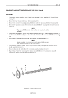
Install roller pin (2) and roller (3) on intake cam follower (4).
2.
Using 0.006 in. (0.15 mm) feeler gauge between intake cam follower (4) and roller (3), install roller
pin (2) on intake cam follower (4) and roller (3). Secure roller pin (2) to intake cam follower (4)
with roll pin (1).
NOTE
All camshaft follower housings are assembled in the same
manner. Repeat step 3 for remaining cam follower housings.
Ensure injector cam follower is in center position and that cam
follower pushrod sockets are on the same side as dowel holes in
housing.
3.
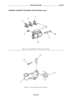
Install two exhaust camshaft followers (6), injector camshaft followers (5), intake camshaft
followers (4), and camshaft follower shafts (8) on camshaft follower housing (9).
NOTE
Expansion plugs should be at least flush with edge of hole or
not more than 0.010 in. (0.254 mm) below edge of hole.
Apply light coat of cup plug sealant to expansion plug hole in
each end.
4.
Using press and mandrel, install two new expansion plugs (7) on ends of camshaft follower
housing (9).
5.
Install two screws (10) securing camshaft follower shaft (8) on camshaft follower housing (9).
6.
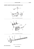
Install orifice plug (11) and keyway (14) on camshaft (15). Tighten orifice plug (11) 5–10 lb-ft
(7–13 N
•
m).
WARNING
Use insulated gloves when handling heated camshaft drive
gear. Failure to observe this warning may result in injury to
personnel.
CAUTION
Do not use cutting torch to heat camshaft gear; damage will
result.
7.
Heat camshaft gear (12) evenly in oven to 400º F (209° C).
8.
Using press, install hot camshaft gear (12), new thrust bearing (13), and keyway (14) on
camshaft (15).
Back to Top


