TM-9-2815-225-34-P - Page 30 of 736
TM 9-2815-225-34&P
0003 00
0003 00-4
THEORY OF OPERATION (Contd)
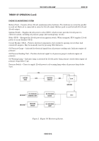
ENGINE OIL MONITORING SYSTEM
Battery Pack – Consists of four 12-volt, maintenance-free batteries. Two batteries are wired in parallel
in each set. Each set is connected in series for 24-volt output. Battery pack is used for both 12-volt and
24-volt output.
Ignition Switch – Supplies 24-volt power to relay (RY-9), which in turn provides 12-volt power to
electrical system, including oil pressure gauge and warning lamp circuits.
Relay (RY-9) – Energized by 24-volt power from ignition switch. When energized, RY-9 supplies 12-volt
power to circuit breaker (CB-2).
Circuit Breaker (CB-2) – Protects electrical components of oil system by opening circuit when load
exceeds 20 amperes. May be manually reset by pressing CB-2 button in.
Oil Pressure Gauge – Activated by electrical signal from oil pressure sending unit. Indicates engine oil
pressure.
Oil Pressure Sending Unit – Provides electrical signal to oil pressure gauge to indicate engine oil
pressure.
Oil Warning Lamp – Indicator lamp is activated by 12-volt power from pressure switch when engine oil
pressure drops below 5 psi.
Pressure Switch – Closes to supply 12-volt power to oil warning lamp when oil pressure drops below
5 psi.
Figure 2. Engine Oil Monitoring System.
BATTERY
PACK
IGNITION
SWITCH
RY-9
GROUND
GROUND
GROUND
CB-2
12V
24V
24V
OIL WARNING
LAMP
OIL PRESSURE
GAUGE
PRESSURE
SWITCH
OIL PRESSURE
SENDING UNIT
Back to Top

