TM-9-2815-225-34-P - Page 31 of 736
TM 9-2815-225-34&P
0003 00
0003 00-5
THEORY OF OPERATION (Contd)
ENGINE RETARDER BRAKE CONTROL
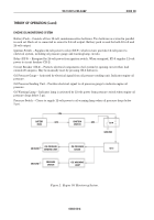
Battery Pack – Consists of four 12-volt, maintenance-free batteries. Two batteries are wired in parallel
in each set. Each set is connected in series for 24-volt output. Battery pack is used for both 12-volt and
24-volt output.
Ignition Switch – Supplies 24-volt power to relay (RY-9), which in turn provides 12-volt power to
electrical system, including engine retarder brake circuit.
Relay (RY-9) – Energized by 24-volt power from ignition switch. When energized, RY-9 supplies 12-volt
power to circuit breaker (CB-2).
Circuit Breaker (CB-2) – Protects electrical components of engine retarder brake circuit by opening
when load exceeds 20 amperes. May be manually reset by pressing CB-2 button in.
Foot Switch – Allows driver to activate engine brake circuit with left foot. When depressed, switch
supplies 12-volt power through CB-2, throttle switch, and engine retarder switch to energize selected
solenoid valve(s).
Throttle Switch – Switch is open when accelerator pedal is pressed down to prevent activation of
engine retarder brake. Activating arm on fuel pump lever closes switch when accelerator is disengaged.
Engine Retarder Switch – Three-position switch allows driver to select engine braking for two cylinders
(LOW), four cylinders (MED), or six cylinders (HIGH). Depressing pedal-actuated foot switch completes
12-volt power circuit to energize one, two, or three solenoids.
Solenoid Valves – Operate engine braking mechanism when activated.
Figure 3. Engine Retarder Brake Controls.
BATTERY
PACK
IGNITION
SWITCH
RY-9
CENTER ENGINE
SOLENOID VALVE
FRONT ENGINE
SOLENOID VALVE
REAR ENGINE
SOLENOID VALVE
GROUND
GROUND
GROUND
GROUND
CB-2
FOOT SWITCH
ENGINE
RETARDER
SWITCH
THROTTLE
SWITCH
Back to Top

