TM-9-2815-225-34-P - Page 322 of 736
TM 9-2815-225-34&P
0036 00
0036 00-6
FUEL GEAR PUMP (Contd)
ASSEMBLY
NOTE
Lubricate all parts, seals, seal rings, and O-rings with
lubricating oil before installation.
1.
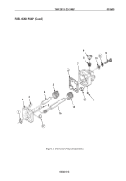
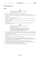
Using press, install two new bearing sleeves (15) in gear body (7).
2.
Using press, install two new bearing sleeves (15) and new dowel ring (1) in gear cover (2).
3.
Using pressurizing valve driver, install new pressure valve (18) 0.015 in. (0.381 mm) below face of
gear cover (2).
4.
Install two dowel pins (3) in gear cover (2).
5.
Using press, install drive gear (16) on drive shaft (17) 0.680–0.690 in. (17.272–17.526 mm) from
end of drive shaft (17).
6.
Using press, install idler gear (5) on idler shaft (4) 0.680–0.690 in. (17.272–17.526 mm) from end
of idler shaft (4).
7.
Install idler shaft (4) with idler gear (5) attached and drive shaft (17) with drive gear (16)
attached in gear cover (2).
NOTE
Location of notches or ridges on gear body and gear cover
determine pump rotation.
When a right-hand rotation pump is being assembled, place
driven gear shaft of gear pump in pocket nearest locating
notches or ridges. Place driving gear shaft in other pocket. The
dowel ring is always located around drive shaft.
8.
Align notches in gear cover (2) with notches on gear body (7) and install new gasket (6) and gear
cover (2) on gear body (7) with two screws (12), new lockwashers (11), and washers (10). Tighten
screw (12) 11–13 lb-ft (15–18 N
•
m).
9.
Apply pipe sealant to pipe plug (14) and install in gear body (7). Tighten pipe plug (14) 10–13 lb-ft
(14–18 N
•
m).
10.
Install adapter (8) and fuel supply elbow (9) on gear body (7).
11.
Using dial indicator, measure drive shaft (17) backlash. Backlash should be 0.001–0.004 in.
(0.0254–0.1016 mm). If correct backlash cannot be obtained, disassemble fuel gear pump (13) and
replace idler gear (5) and drive shaft gear (16).
12.
Using dial indicator, measure drive shaft (17) end play. End play should be between
0.0009–0.0015 in. (0.0228–0.038 mm). If correct end play cannot be obtained, disassemble fuel
gear pump (13) and replace gear body (7) and drive shaft (17).
13.
Install fuel gear pump (13) on fuel pump housing. Refer to WP 0040 00.
Back to Top


