TM-9-2815-225-34-P - Page 330 of 736
TM 9-2815-225-34&P
0038 00
0038 00-2
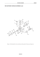
FUEL PUMP FRONT COVER AND GOVERNOR (Contd)
DISASSEMBLY
NOTE
Be careful not to lose spring and shims during removal of
weight-assist plunger. Keep weight-assist plunger, shims, and
spring together.
1.
Remove weight-assist plunger (13), shims (12), and spring (11) from governor (14). Discard
spring (11).
2.
Remove screw (20) and washer (21) securing fuel pump drive coupling (22) on fuel pump drive
shaft (24).
3.
Using puller, remove fuel pump drive coupling (22), tachometer drive gear (23), and coupling
key (19) from fuel pump drive shaft (24).
4.
Remove retaining ring (8) securing fuel pump drive shaft (24) in fuel pump front cover (16).
Discard retaining ring (8).
5.
Remove fuel pump drive shaft (24), with bearing (7), fuel pump drive gear (9), and coupling (10)
attached, from fuel pump front cover (16).
6.
Using press, remove coupling (10) and fuel pump drive gear (9) from fuel pump drive shaft (24).
7.
Using press, remove bearing (7) from fuel pump drive shaft (24). Discard bearing (7).
8.
Remove tachometer drive housing (2) from fuel pump front cover (16).
9.
Using brass punch and hammer, remove tachometer drive shaft (1), with seal (3), spacer (4),
bushing (5), and gear (6) attached, from fuel pump front cover (16).
10.
Remove gear (6), bushing (5), spacer (4), and seal (3) from tachometer drive shaft (1). Discard seal
(3) and bushing (5).
11.
Using press, remove two shaft seals (17) and (18) from fuel pump front cover (16). Discard shaft
seals (17) and (18).
12.
Using brass punch and hammer, remove governor bushing (15) from fuel pump front cover (16).
Discard governor bushing (15).
CLEANING AND INSPECTION
1.
For general parts cleaning information, refer to CLEANING, WP 0051 00.
2.
For general parts inspection information, refer to INSPECTION, WP 0051 00.
NOTE
Replace any part that does not pass visual inspection or that is
outside specified wear limits.
3.
Inspect weight-assist plunger (13), governor (14), fuel pump drive coupling (22), tachometer drive
gear (23), fuel pump drive shaft (24), fuel pump drive gear (9), coupling (10), tachometer drive
housing (2), gear (6), tachometer drive shaft (1), and fuel pump front cover (16) for cracks, breaks,
excessive wear, and other damage.
4.
Inspect fuel pump drive shaft (24) and tachometer drive shaft (1) for scoring, wear, grooves, and
other damage.
Back to Top


