TM-9-2815-225-34-P - Page 339 of 736
TM 9-2815-225-34&P
0039 00
0039 00-5/6 blank
FUEL PUMP MAIN HOUSING (Contd)
ASSEMBLY (Contd)
18.
Install fuel filter screen (8), filter spring (7), new cap seal ring (6), and filter screen cap (5) on
housing (9). Tighten filter screen cap (5) 8–12 lb-ft (11–16 N
•
m).
19.
Install tapered stud (31) with jamnut (10) and threaded stud (11) on housing (9).
20.
Apply lubricating oil to new O-ring (13) and install AFC needle valve (12) on housing (9) until
AFC needle valve (12) bottoms out.
21.
Install throttle shaft (22) on stop (21) and secure with setscrew (15). Do not tighten setscrew (15)
at this time.
22.
Apply lubricating oil to new O-ring (16) securing fuel adjusting screw (20), and install O-ring (16)
on throttle shaft (22) about six rotations. Ensure fuel hole in throttle shaft (22) is open.
23.
Apply lubricating oil to new O-ring (23) and install throttle shaft (22) in housing (9) with
counterbore of fuel port facing down. Ensure setscrew (15) in stop (21) faces upward. Tighten
setscrew (15) 7–9 lb-ft (9–12 N
•
m).
NOTE
New throttle shaft ball, throttle shaft cover, and two drive
screws will be installed after fuel pump has been calibrated.
24.
Install new retaining ring (33) on end of throttle shaft (22).
25.
Install fuel pump main housing to fuel pump (WP 0040 00).
END OF WORK PACKAGE
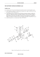
Figure 3. Main Housing Assembly.
Figure 4. Main Housing Assembly.
33
6
13
17
16
23
5
7
8
9
10
11
12
14
15
18
19
20
21
22
10
1
25
24
26
27
28
29
30
31
34
32
35
1
2
3
4
45
43
44
42
41
40
39
36
38
37
46
36
58
57
55
54
53
52
51
9
48
47
50
49
56
Back to Top

