TM-9-2815-225-34-P - Page 342 of 736
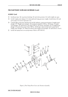
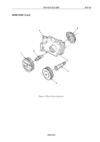
Figure 1. Fuel Pump Front Cover and Governor Installation.
TM 9-2815-225-34&P
0040 00
0040 00-2
FUEL PUMP ASSEMBLY (Contd)
FUEL PUMP FRONT COVER AND GOVERNOR
NOTE
Position governor weight housing carrier horizontally and hold
governor weights while installing fuel pump main housing.
Ensure governor weights are properly engaged with tang on
governor plunger.
1.
Remove fuel pump front cover (3) from mounting plate and ball joint vise.
2.
Install new gasket (4), fuel pump (5), and screw (6) on fuel pump front cover (3). Tighten
screws (6) 9–11 lb-ft (12–15 N
•
m).
3.
Install six washers (7), eight new lockwashers (8), and screws (9) securing fuel pump front cover
(3) on fuel pump (5). Tighten screw (9) 9–11 lb-ft (12–15 N
•
m).
4.
Install new plastic bushing seal (2) and screw (1) on fuel pump front cover (3). Tighten screw (1)
9–11 lb-ft (12–15 N
•
m).
5.
For fuel pump front cover and governor repair, refer to WP 0038 00.
FUEL PUMP GOVERNOR SPRING
1.
Install fuel pump governor spring (13), snapring (17), shims (14) and (15) and spring seat (16), on
guide (12).
2.
Install new gasket (18), spring pack cover (19), four washers (20), and screws (21) on fuel pump
(5). Place screw (21) with lockwire hole in upper right corner of spring pack cover (19). Torque
screws (21) 9–11 lb-ft (12–15 N
•
m).
NOTE
Final calibration and on-engine fuel pump adjustments must
be made prior to installation of new adjusting screw seal and
wire.
3.
Install new adjusting screw seal (11) and wire (10) on cover plug (22).
4.
For fuel pump governor spring repair, refer to WP 0037 00.
2
4
8
5
3
1
9
7
6
BALL JOINT VISE
MOUNTING
PLATE
Back to Top

