TM-9-2815-225-34-P - Page 332 of 736
TM 9-2815-225-34&P
0038 00
0038 00-4
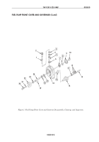
FUEL PUMP FRONT COVER AND GOVERNOR (Contd)
ASSEMBLY
NOTE
Lubricate all parts, seals, seal rings, and O-rings with
lubricating oil before installation.
1.
Install new bushing (5) on tachometer drive shaft (1).
2.
Using press, install gear (6) on tachometer drive shaft (1) until 0.002–0.005-in. (0.050–0.127-mm)
gap between bushing (5) and gear (6) is obtained. Using a feeler gauge, check clearance between
gear (6) and bushing (5). Remove and install gear (6) until correct gear (6) to bushing (5) clearance
is obtained.
3.
Align oil groove in top of bushing (5) with fuel pump drive shaft (1). Using press, install bushing (5)
with tachometer drive shaft (1) and gear (6) attached on fuel pump front cover (16) until fully
seated.
4.
Install spacer (4) on tachometer drive shaft (1) with slotted edge facing down until seated against
top of bushing (5).
5.
Using front cover tachometer seal driver and hammer, install new seal (3) with spring side down in
fuel pump front cover (16).
6.
Install tachometer drive housing (2) in fuel pump front cover (16).
CAUTION
Do not overtighten tachometer drive housing because it will
compress spacer too much and will reduce its effectiveness.
7.
Lubricate fuel pump drive shaft (24) with clean diesel fuel. Using main shaft gear and bearing
installation tool and press, install new bearing (7) on fuel pump drive shaft (24).
8.
Using main shaft gear and bearing installation tool and press, install fuel pump drive gear (9) on
fuel pump drive shaft (24) until fully seated on bearing (7).
9.
Apply lubricating oil to fuel pump drive shaft (24) and bore of coupling (10). Using press, install
coupling (10) on fuel pump drive shaft (24) until fully seated against fuel pump drive gear (9).
10.
Using main shaft seal driver and press, install first new shaft seal (17) in fuel pump front
cover (16) with lip facing back of fuel pump front cover (16).
11.
Using main shaft seal driver and press, install second new shaft seal (18) on fuel pump front cover
(16) with lip facing front of fuel pump front cover (16).
12.
Using oil seal assembly tool and press, install fuel pump drive shaft (24) with bearing (7) and gear
(9) attached in fuel pump front cover (16) until bearing (7) is fully seated. Ensure first shaft seal
(17) and second shaft seal (18) are not moved during assembly.
13.
Install new retaining ring (8) on fuel pump drive shaft (24) between fuel pump drive gear (9) and
bearing (7). Look through holes in fuel pump drive gear (9) to ensure retaining ring (8) is properly
seated in groove.
14.
Install coupling key (19) in fuel pump drive shaft (24).
15.
Position tachometer drive gear (23) and fuel pump drive coupling (22) on fuel pump drive shaft (24).
Using press, slowly install tachometer drive gear (23) and fuel pump drive coupling (22) on fuel
pump drive shaft (24) until fully seated. Ensure tachometer drive gear (23) and tachometer gear
teeth are properly aligned.
16.
Install screw (20) and washer (21) in fuel pump drive shaft (24). Tighten screw (20) 5 lb-ft (7 N
•
m).
17.
Using press, install new governor bushing (15) in fuel pump front cover (16).
Back to Top

