TM-9-2815-225-34-P - Page 338 of 736
TM 9-2815-225-34&P
0039 00
0039 00-4
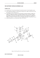
FUEL PUMP MAIN HOUSING (Contd)
ASSEMBLY
NOTE
Lubricate all parts, seals, seal rings, and O-rings with
lubricating oil before installation.
1.
Install two screws (3) and nameplate (2) on housing (9).
2.
Install two dowels (25) and (35), two AFC plug balls (34), and tachometer drive bushing (32) on
housing (9).
3.
Install governor barrel (26) and spring pack (27) on housing (9).
4.
Install five pipe plugs (1) and (4), and roll pin (24) on housing (9). Tighten pipe plugs (1) and (4)
5–8 lb-ft (7–11 N
•
m).
NOTE
Put small diameter of spring on shoulder end of plunger with
twisting motion to avoid damaging spring.
5.
Install torque spring (28) and three shims (29) on governor plunger (30).
6.
Install governor plunger (30) on housing (9).
NOTE
Round end of retainer washer must be against bellows when
assembled. If bellows has a part number, it must face toward
piston.
Ensure all parts are aligned and do not twist bellows.
7.
Install new gasket washer (43), retainer washer (44), new bellows (45), AFC piston (46), piston
spacer (47), and nut (48) on air fuel control piston insert (42). Tighten nut (48) 30–40 lb-ft
(41–54 N
•
m).
8.
Apply lubricating oil to new O-ring (49) and install throttle plunger (50) on air fuel control piston
insert (42). Ensure that threaded end of throttle plunger (50) is flush with outer edge of piston
insert (42).
9.
Tighten jamnut (41) on throttle plunger (50) until finger-tight.
NOTE
Earlier pump models did not require a barrel spring.
10.
Install barrel spring (51) in housing (9).
11.
Apply lubricating oil to three new O-rings (53), (54), and (55) and install O-rings (53), (54),
and (55) with spring (50) on barrel (52).
12.
Using press, install barrel (52) in housing (9) and secure with new retaining ring (56).
13.
Apply 10 lb (4.54 kg) of load on spring (58) and AFC shim (57).
14.
Compress spring 0.300 in. (7.62 mm) more than dimension of step 13 and install AFC shim (57)
and spring (58) on housing (9).
15.
Install bellows (45) down between AFC piston (46) and housing (9) and line up holes in
bellows (45) with holes in housing (9). Ensure bellows (45) is flat where it touches housing (9).
16.
Install fuel control cover (40) on bellows (45) and housing (9) with two screws (38), drilled head
screw (37), and three washers (36). Do not tighten screws (38).
17.
Ensure check ball is loose and hole near bottom of check valve (39) is not plugged. Turn check
valve (39) on top of fuel control cover (40). Tighten fuel control cover (40) 5 lb-ft (7 N
•
m).
Back to Top


