TM-9-2815-225-34-P - Page 344 of 736
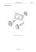
Figure 3. Fuel Gear Pump Installation.
TM 9-2815-225-34&P
0040 00
0040 00-4
FUEL PUMP ASSEMBLY (Contd)
FUEL GEAR PUMP
NOTE
Use correct gasket in step 2 and ensure that it is positioned
correctly. Ensure main housing fuel holes match gear pump
holes.
1.
Install fuel supply elbow (3) and adapter (4) on gear body (2).
2.
Position notch in upper right-hand corner and install fuel gear pump (7) and new gasket (1) on
fuel pump (8). Secure with four screws (6) and new lockwashers (5). Tighten screws (6) 11–13 lb-ft
(15–18 N
•
m).
NOTE
Check that gear pump shaft rotates freely.
3.
For fuel gear pump repair, refer to WP 0036 00.
FUEL DAMPER AND HEAD
1.
Apply light coat of lubricating oil on new rectangular seals (9) and (14) on filter head (10).
2.
Install filter head (10) on fuel pump (8) and secure with four screws (13), new lockwashers (12),
and washers (11). Tighten screws (13) 11–13 lb-ft (15–18 N
•
m).
3.
For fuel damper and head repair, refer to WP 0035 00.
SOLENOID VALVE
1.
Apply light coat of lubricating oil on new rectangular ring seal (21) on solenoid valve (20).
2.
Install solenoid valve (20) on fuel pump (8) and secure with two screws (18), new
lockwashers (17), and washers (19).
3.
Install plug (16) on valve body (15).
4.
For solenoid valve repair, refer to WP 0034 00.
1
5
6
3
2
7
8
4
Back to Top


