TM-9-2920-225-34 - Page 40 of 262
TM 9-2920-225-34
g.
Replacement.
FRAME 1
I
1.
2.
3.
4.
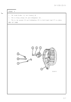
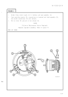
Slide intermediate housing (1) over rotor and fan assembly (2) with leads
of stator (3) alined with slot in intermediate housing.
Aline scribe marks on intermediate housing ( 1), stator ( 3), and drive end
housing (4) .
Put in six long screws (5) and lockwashers (6).
Put retaining ring (7) in place and put preformed packing (8) around outer
bore of intermediate housing ( 1).
NOTE
Follow-on Maintenance Action Required:
1.
Replace end housing assembly and insulator. Refer
to para 2-4g.
2.
Replace regulator assembly. Refer to para 2- 3
C
.
END OF TASK
TA103523
2-24
Back to Top


