TM-9-2920-242-35 - Page 10 of 110
CHAPTER 1
INTRODUCTION
Section I. GENERAL
1. SCOPE
a. This technical manual contains instruc-
tions for direct support, general support, and
depot maintenance of the starter assembly, FSN
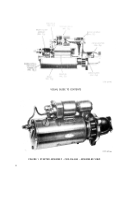
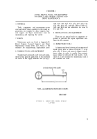
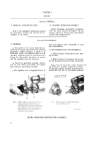
2920-226-6545 (fig. 1). It contains descriptions
of, and procedures for, troubleshooting, dis-
assembly, inspection, repair, and assembly of
the starter.
b. Appendix I contains a list of current ref-
erences applicable to the starter.
c. Appendix II contains an illustrated list of
repair parts allocated to Direct and General
Support and Depot Maintenance.
d. Any errors or omissions will be brought
to the attention of the Commanding General,
U.S. Army Tank-Automotive Center, 28251 Van
Dyke, Warren, Michigan, 48090, ATTN: SMOTA-
MT, using DA Form 2028.
2. DIRECT SUPPORT, GENERAL SUPPORT,
AND DEPOT MAINTENANCE ALLOCA-
TION
Refer to maintenance allocation chart in
pertinent vehicle organizational maintenance
manual.
3. FORMS, RECORDS, AND REPORTS
For current and complete listing of all au-
thorized forms, refer to current issue of DA
Pamphlet 310-2. TM 38-750 contains instruc-
tions on use of forms for records and reports.
Section II. DESCRIPTION AND DATA
4. DESCRIPTION
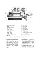
Note. The key letters shown in parentheses
refer to figure 2.
a. Description. This electrical starter is a
heavy-duty, 24 volt, insulated, waterproof, fun-
(2)
gus and corrosion resistant, solenoid-operated,
enclosed shift-lever-type engine starter with
eight brushes retained in four brush holders.
The drive clutch is a heavy-duty overrunning
type and the pinion clearance is adjustable. The
principal components of the starter assembly
are the frame assembly (X), armature (W),
commutator end plate assembly (Z), brush
holder assembly (CC), brushes (B), drive clutch
assembly (T), drive housing (Q), solenoid relay
assembly (G), lever housing (M), shift lever
(3)
(P), and solenoid plunger (J).
(1) Frame assembly. The frame assembly
(X) consists of the field coils (D), pole
shoes (E), and field coil terminal stud
(C), all supported by a heavy steel
frame. The field coils are secured to
the frame by the pole shoes and eight
pole shoe screws (V). The coils are
connected to the field coil terminal stud
which is insulated from the frame. The
frame has screw thread openings for
mounting the solenoid relay.
Armature. The armature (W) is made
of copper and laminated steel assem-
bled on a steel shaft. It is supported by
three sleeve bearings (R, U, and BB).
The armature has straight splines on
the drive end of the shaft which engage
splines on the drive clutch assembly
(T). A commutator, located at the brush
end of the armature, is the electrical
point of contact of the armature.
Commutator end plate assembly. The
commutator end plate assembly (Z)
serves as an end closure for the frame
and a bearing support for the armature.
It also serves as a support for the brush
holder assembly (CC). The brush holder
assembly is a component part of the
commutator end plate assembly.
1
Back to Top

