TM-9-2920-242-35 - Page 18 of 110
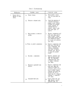
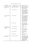
Malfunction
5.
Continued
6.
Pinion will not over-
ride.
7.
Starter vibrates dur-
ing operation.
8.
Excessive arcing of
brushes.
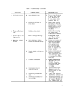
Table I. Troubleshooting - Continued
Probable causes
b.
c.
a.
b.
c.
d.
e.
f.
Loose adjustment nut.
Binding in shift lever or
drive clutch.
Defective drive clutch.
Worn or damaged bearings.
Worn, binding, or broken
brushes or defective springs.
Scored, pitted, or dirty com-
mutator.
Eccentric commutator.
Commutator mica not
undercut properly.
Shorted or grounded field
coils.
Shorted or grounded arma-
ture windings.
9
Corrective action
b.
c.
a.
b.
c.
d.
e.
f.
Remove inspection plug
(c, fig. 31, step 5) and
check adjustment nut.
If loose, adjust pinion
clearance (par. 36).
Remove lever housing
(par. 18) and check for
defective lever or clutch.
Replace defective parts
as required (pars. 21,
34 and 35).
Remove drive housing
and replace drive
clutch (pars. 18 and 35).
Disassemble starter
(par. 18) and replace
defective bearings.
Remove commutator end
plate (par. 18c) and in-
spect brushes. Check
brush spring tension
(fig. 10). Install new
brush kit (par. 35c) if
parts are defective and
re-seat brushes.
Remove commutator end
plate (par. 18c) and in-
spect commutator. Clean
commutator (par. 25c)
or resurface commutator
(par. 27d).
Remove armature (par.
18c) and check runout
(fig. 22). Resurface
commutator (par. 27d)
or replace armature
(par. 35c).
Remove armature (par.
18c) and inspect com-
mutator. Under cut mica
(par. 27c).
Inspect field coils (par.
26i). Replace coils (par. 30).
Remove armature (par. 18c)
and check for grounds (fig.
20) or shorts (fig. 21). Re-
place armature (par. 35c).
Back to Top

