TM-9-2920-242-35 - Page 23 of 110
para. 41e
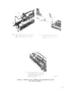
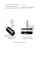
FIGURE 8. REMOVING SOLENOID RELAY.
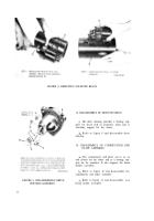
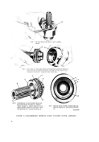
FIGURE 9. DISASSEMBLING DRIVE
HOUSING ASSEMBLY.
19. DISASSEMBLY OF DRIVE HOUSING
a. The drive housing provides a bearing sup-
port for drive end of armature shaft and is
attaching support for the starter.
b . Refer to figure 9 and disassemble drive
housing.
20. DISASSEMBLY OF COMMUTATOR END
PLATE ASSEMBLY
a . The commutator end plate serves as an
end closure for the frame and as a bearing sup-
port for the armature. It also supports the brush
holder assembly.
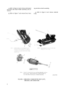
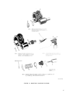
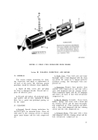
b . Refer to figure 10 and disassemble th e
commutator end plate assembly.
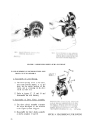
c . Refer to figure 11 and disassemble an d
brush holder assembly.
14
Back to Top

