TM-9-2920-242-35 - Page 27 of 110
para. 41e
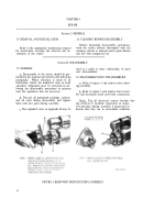
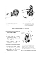
FIGURE 13. REMOVING SHIFT LEVER AND SHAFT.
21. DISASSEMBLY OF LEVER HOUSING AND
DRIVE CLUTCH ASSEMBLY
a. Disassembly of Lever Housing.
(1)
(2)
The lever housing serves as the arma-
ture center bearing support, as an end
plate for the motor portion of the
starter, and as a housing for the drive
clutch and shift lever.
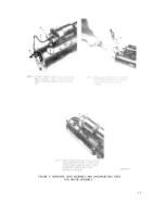
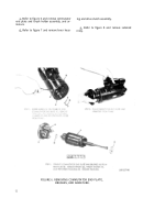
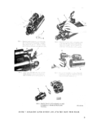
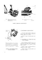
Refer to figures 12, 13, and 14 and
disassemble the lever housing.
b. Disassembly of Drive Clutch Assembly.
(1)
(2)
18
The drive clutch assembly transmits
the torque developed by the armature
to the engine flywheel ring gear.
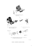
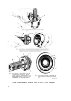
Disassemble the drive clutch assembly
as shown in figures 15 and 16.
FIGURE 14. DISASSEMBLING LEVER HOUSING
Back to Top

