TM-9-2920-242-35 - Page 34 of 110
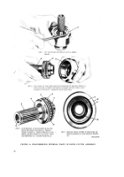
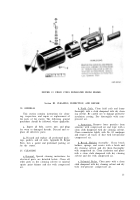
FIGURE 20. TESTING ARMATURE FOR
(4)
(5)
GROUNDS.
ture slowly in the growler. A short cir-
cuit will pull the steel strip tightly
against the armature core and cause the
strip to vibrate. If a short circuit is
found, the armature must be replaced.
Inspect armature shaft and commutator
for runout using a lathe or "V" blocks
and a dial indicator (fig. 22). If the run-
out does not conform to wear limits
(par. 41f), the commutator must be re-
surfaced providing the diameter will not
be below the limits specified in wear
limits. If refinished diameter of com-
mutator exceeds the limit, the armature
must be replaced.
Inspect armature shaft splines for wear
or damage. Replace the armature if the
splines are defective.
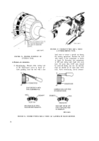
FIGURE 21. TESTING ARMATURE FOR
SHORT CIRCUITS USING A GROWLER.
color. If the contact surface is rough,
pitted, scored, burned, or coated with
hard carbon or oil, the commutator must
be resurfaced. If mica is not 0.025 to
0.032 inch below surface of commutator,
it must be undercut to the correct depth.
(6)
Inspect the commutator contact surface.
A satisfactory condition is indicated by
an even, highly burnished, dark-copper
FIGURE 22. CHECKING
COMMUTATOR RUNOUT.
25
Back to Top


