TM-9-2920-242-35 - Page 40 of 110
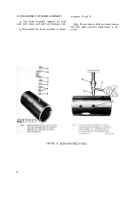
c. Refer to figure 18, step 1 and install gas-
ket (G), two nonmetallic washers (F), 0.520 ID,
7/8 OD, 0.031 thick flat washer (E), 1/2-inch
hex nut (D), field coil terminal-to-solenoid relay
connector (C), 1/2-inch lock washer (B), and
1/2-inch hex nut (A).
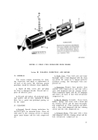
d. Varnish inside of frame and coil assembly.
Leave 0.38 inch from each end of frame free of
varnish. Allow varnish to dry thoroughly before
assembling starter.
31. ASSEMBLY OF SOLENOID RELAY
Note. The key letters shown below in paren-
theses refer to figure 17, step 3 except where
otherwise indicated.
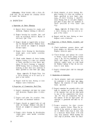
a. Install terminal (G) on motor terminal stud
(E) (short stud). Install motor terminal stud,
battery terminal stud (F), terminal stud insula-
tion strip (H), and terminal plate (J) with motor
terminal stud in plate hole marked "MOTOR".
Install one insulating bushing (K), one insulator
(L), one 0.516 ID, 7/8 OD, 1/32 thick flat washer
(M), two 1/2-inch lock washers (N), one 1/2-
inch, 0.310 thick hex nut (P), and 1/2-inch,
0.438 thick hex nut (Q) on each terminal stud.
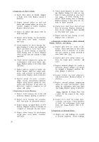
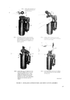
b. Refer to figure 28 and complete assembly
of solenoid relay.
FIGURE 28. ASSEMBLING SOLENOID RELAY.
31
Back to Top


